Multiple extruder configuration

Inactive Publication Date: 2006-03-28
BERSTORFF GMBH
View PDF21 Cites 7 Cited by
  • Summary
  • Abstract
  • Description
  • Claims
  • Application Information

AI Technical Summary

Benefits of technology

[0008]The invention may create a multiple-extruder configuration which, on the one hand, allows a high mean residence time for processes that are limited by residence time and, on the other hand, allows a high torque relative to the sc

Problems solved by technology

There are many processes used in compounding, which are limited either by torque or residence time.
In this case, the speeds of the twin-screw extruder must be kept as low as possible, since otherwise the very high viscosity of the mixture leads to temperature problems due to mechanical dissipation in the mixture.
However, this causes the temperature of the compound to rise again.
The machine length with twin-screw extruders

Method used


Image

  • Multiple extruder configuration
  • Multiple extruder configuration
  • Multiple extruder configuration

Examples


Example

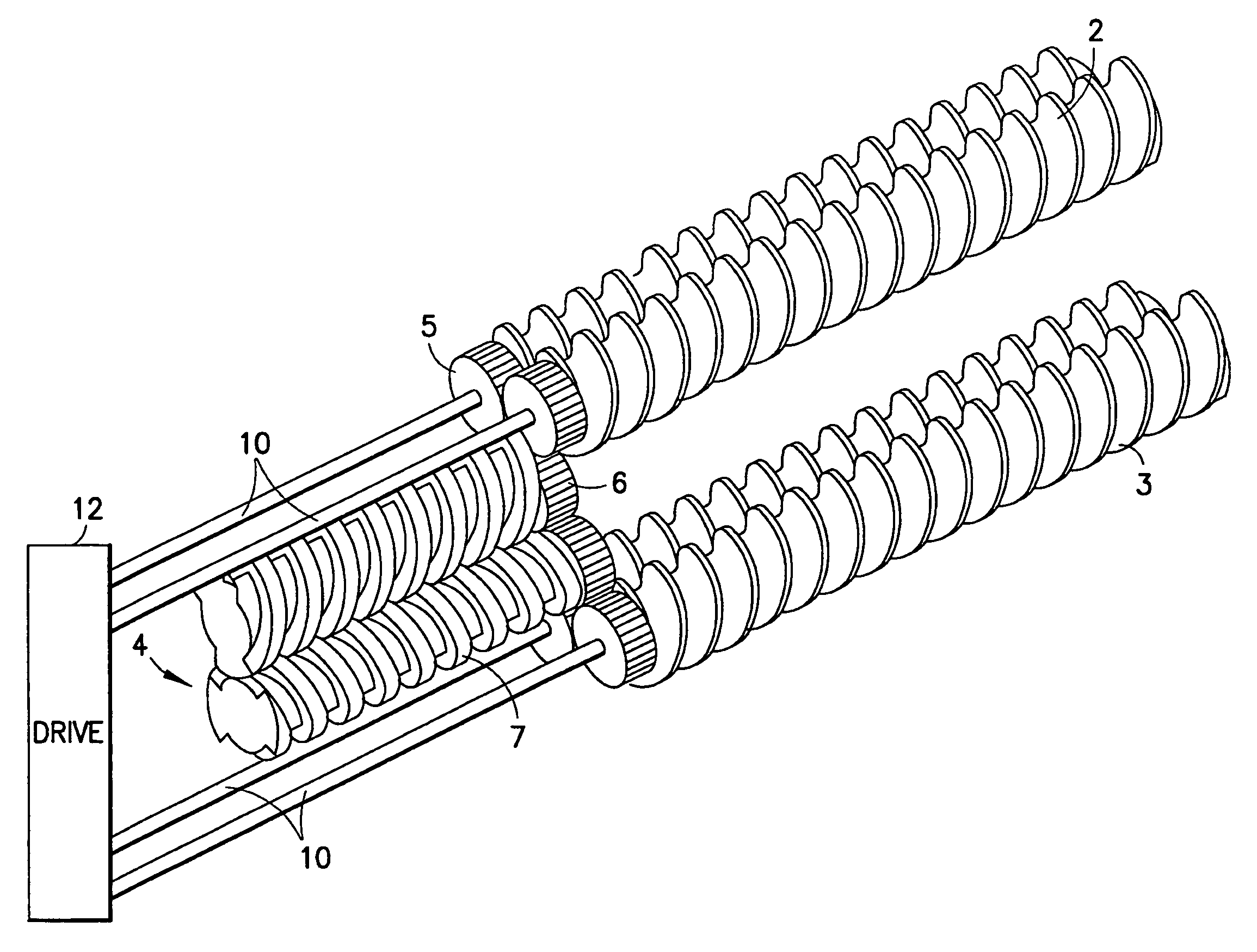
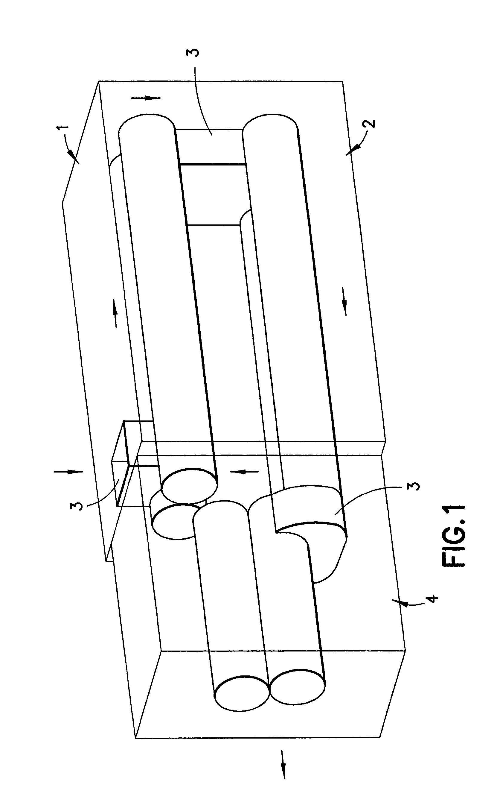
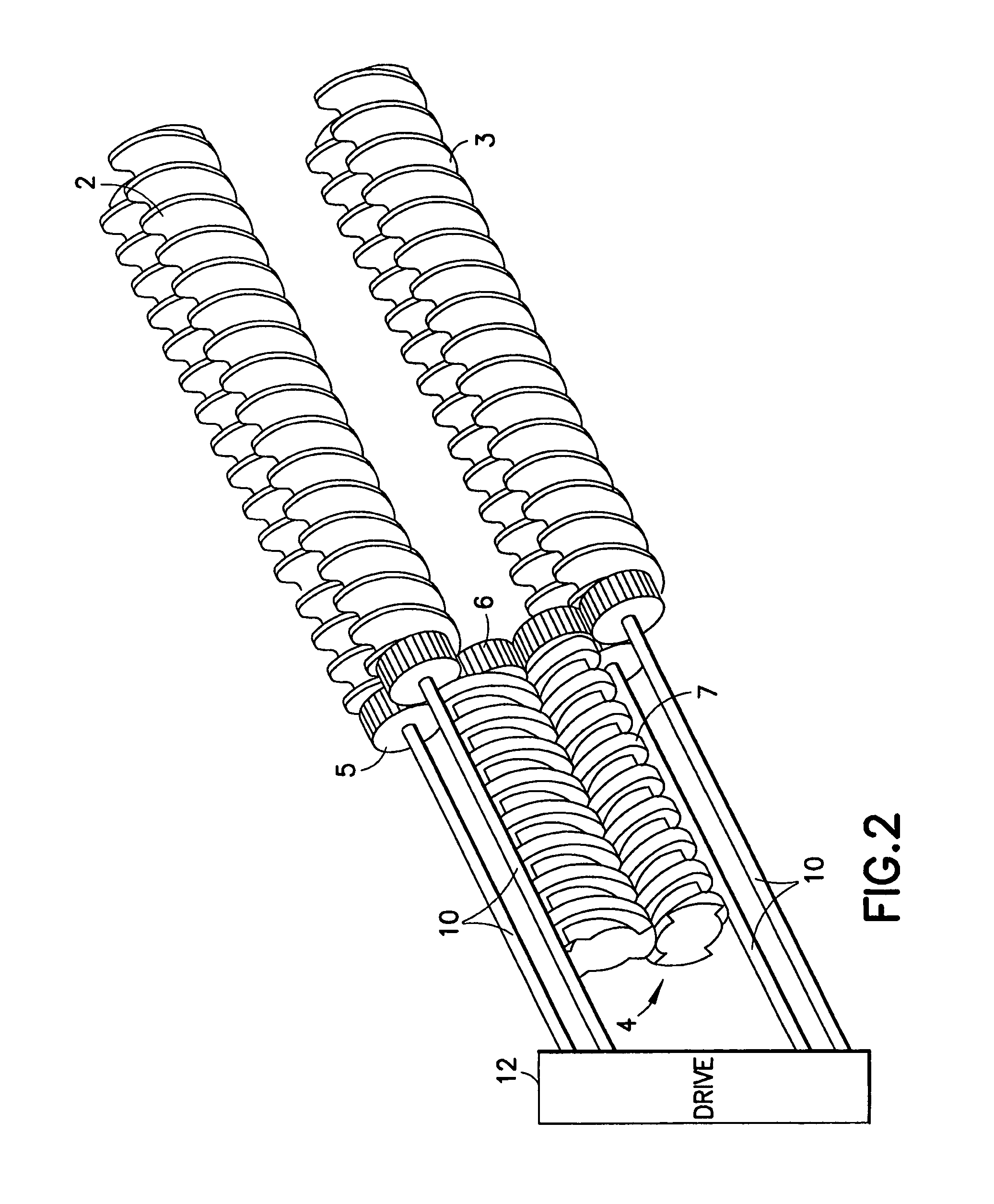
[0018]FIG. 1 shows a multiple-extruder configuration, in which the two co-rotating twin-screw extruders 1, 2 are arranged parallel to, and one above, the other. The material to be extruded is fed into the upper extruder 1 at first feeder 3a. After it has been pushed Through the first extruder 1, it is fed into the second extruder 2 via second feeder 3b and finally reaches the counter-rotating twin-screw extruder 4 via a third feeder 3c, which is designed as an expeller. In FIGS. 2 and 3, the material flows in the same direction as in the design shown in FIG. 1. They merely show different types of drives. In FIG. 2, the screw shafts of the co-rotating extruders 2 and 3 are driven by four drive shafts 10 of a drive 12. Gears 5, which are mounted at the end of each of the screw shafts, drive two additional gears 6, which are mounted on screw shafts 7 of the following counter-rotating twin-screw extruder 4.

[0019]In the design shown in FIG. 3, the drive 12 includes six drive shafts 10 su...


PUM

PropertyMeasurementUnit
Pressureaaaaaaaaaa

Abstract

The invention concerns a multiple-extruder configuration in which two co-rotating twin-screw extruders and a counter-rotating twin screw extruder are connected to each other with respect to the flow of material.

Description

CROSS REFERENCE TO RELATED APPLICATIONS[0001]This is a U.S. national stage of application under 35 U.S.C. §371 of international stage application No. PCT / DE02 / 04503, filed on Dec. 5, 2002. Priority is claimed under 35 U.S.C. §119(a) and under 35 U.S.C. §365(b) from German Patent Application No. 101 62 076.4, which was filed on Dec. 7, 2001, and from which priority was properly claimed in the aforementioned international stage application.FIELD OF INVENTION[0002]The invention concerns a multiple-extruder configuration with the use of twin-screw extruders.BACKGROUND OF THE INVENTION[0003]There are many processes used in compounding, which are limited either by torque or residence time.[0004]Example of a Process Limited by Torque: continuous mixing of rubber compounds. In this case, the speeds of the twin-screw extruder must be kept as low as possible, since otherwise the very high viscosity of the mixture leads to temperature problems due to mechanical dissipation in the mixture. Of c...

Claims


Application Information

Patent Timeline
IPC IPC(8): B29B7/74B29B7/46B29C48/03B29C48/38B29C48/385B29C48/395B29C48/40B29C48/405B29C48/41
CPCB29C47/0004B29C47/366B29C47/50B29C47/0009B29C47/0801B29C47/402B29K2021/00B29C47/38B29B7/7495B29C48/022B29C48/03B29C48/252B29C48/385B29C48/395B29C48/402B29C48/38B29B7/489B29C48/41B29C48/405B29C48/40B29B7/485B29B7/487
Inventor UPHUS, REINHARD
Owner BERSTORFF GMBH
Why Eureka
Try Eureka