
Container comprising an inner pouch

a container and inner pouch technology, applied in the field of containers, can solve the problems of deteriorating the quality unable to discharge part of the contents of the container, and high undesired air entering the inner pouch,

Inactive Publication Date: 2006-03-28
CAPLAST GMBH
View PDF8 Cites 26 Cited by
  • Summary
  • Abstract
  • Description
  • Claims
  • Application Information

AI Technical Summary

Benefits of technology

[0012]The outer wall and the inner pouch may be firmly connected to each other at individual places, which is preferably the case in the bottom area of the container, so that the inner pouch does not contract in axial direction, but definitely contracts in radial direction, which is of advantage to a complete discharge of the contents of the container. Suitably, outer wall and inner pouch are also firmly interconnected in the area of the container opening, i.e. e.g. on a container neck, so that an outwardly tight inner space is created between the outer wall and the inner pouch.

Problems solved by technology

The entry of air into the inner pouch is highly undesired because this may deteriorate the quality of the contents of the container and because the liquid level in the inner pouch may fall to such an extent that part of the contents of the container can no longer be discharged, for instance because of the fact that the liquid level falls below the inlet opening of the suction tube of a pump.

Method used


Image

  • Container comprising an inner pouch
  • Container comprising an inner pouch

Examples


Embodiment Construction

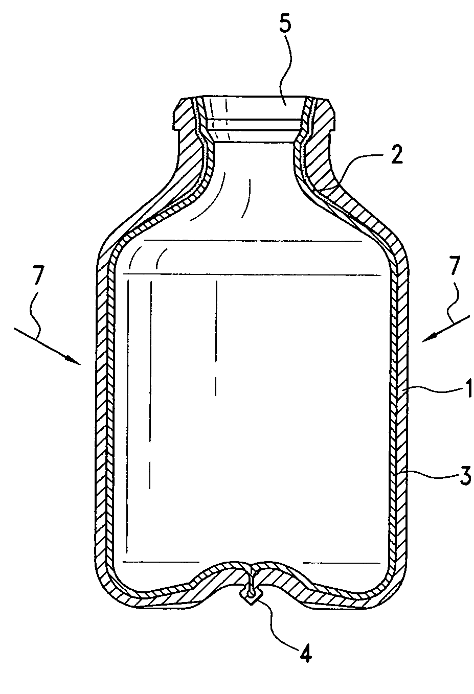
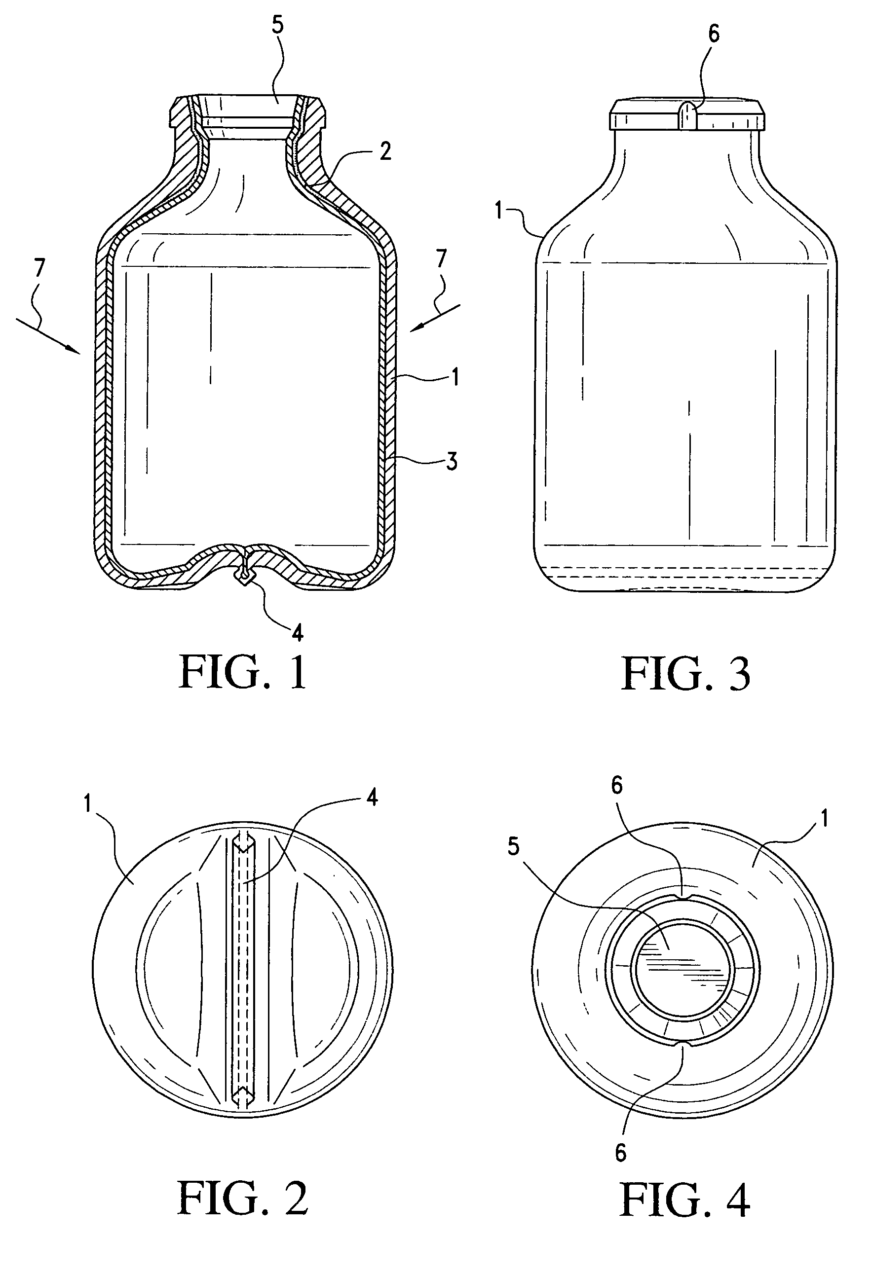
[0025]The container shown in the FIGS. 1–4 is produced in a coextrusion type blow molding process from a three-layered tubular blank. The outer layer 1 consists of a relatively rigid plastic material so that said outer wall of the container substantially maintains its dimensional stability even if the contents of the container are discharged. The intermediate layer 2 comprises a mixture of citric acid and sodium bicarbonate, while the inner pouch 3 consists of a non-rigid plastic material.

[0026]On the bottom, as shown in FIGS. 1 and 2, the mold cavity of the blow mold is designed such that when the blow mold is closed a pinch-off seam 4 of a substantially diamond-shaped cross section is created in which inner pouch 3 is clamped, as shown, partially, in FIG. 1. The squeezing in of inner pouch 3 has the effect that inner pouch 3 cannot contract in axial direction

[0027]In the area of the opening 5 of the container, two vent beads 6 are formed in the outer wall 1. The vent beads prevent...


PUM

PropertyMeasurementUnit
permeableaaaaaaaaaa
shapeaaaaaaaaaa
volumeaaaaaaaaaa

Abstract

A container comprises a substantially dimensionally stable outer wall and an easily deformable inner pouch which gradually contracts upon discharge of the contents of the container. As a result, pressure compensation is provided in the increasing space between the outer wall and the inner pouch. The outer wall and the inner pouch have, therebetween, a layer of a pressure compensating material that expands when acted upon by an agent. The expanding layer comprises, in an exemplary embodiment, citric acid and sodium bicarbonate foam acting against the inner pouch. The foamed pressure-compensating layer supports the inner pouch so that no vacuum is generated in the pouch.

Description

CROSS-REFERENCE TO RELATED APPLICATIONS AND CLAIM TO PRIORITY[0001]This application claims the benefit of and priority to PCT application no. PCT / DE00 / 01849, filed Jun. 7, 2000, the entire disclosure of which is incorporated herein by reference.BACKGROUND OF THE INVENTION[0002]The present invention relates to a container comprising a substantially dimensionally stable outer wall and an easily deformable inner pouch into which a pharmaceutical liquid can e.g. be filled that can be discharged with a pump attached to the neck of the container. However, the contents of the container may also be a cream or a past which is discharged from the opening of the container by compressing the outer wall.[0003]The container may have the shape of a bottle or e.g. of a small tube, its shape being not limited in any way.[0004]There are known containers consisting of a substantially dimensionally stable outer wall and an easily deformable inner pouch which are produced, for example, in a coextrusion ...

Claims


Application Information

Patent Timeline
Patent Type & Authority Patents(United States)
IPC IPC(8): B65D23/02B65D25/16B65D83/14
CPCB65D25/16B65D23/02
Inventor KNEER, ROLAND
Owner CAPLAST GMBH
Learn More