Rolling ball spline slip joint with helically shaped cage

a rolling ball spline and cage technology, applied in the field of manufacture of slip joints, can solve the problems of affecting the structure of the cage is relatively complicated, and the cost of manufacture is high, so as to improve the structure of the cage, improve the efficiency of the operation of the rolling ball spline slip yoke, and improve the effect of the structur

Inactive Publication Date: 2006-03-28
DANA AUTOMOTIVE SYST GRP LLC
View PDF13 Cites 12 Cited by
  • Summary
  • Abstract
  • Description
  • Claims
  • Application Information

AI Technical Summary

Benefits of technology

[0006]This invention relates to an improved structure for a cage for maintaining the balls in a rolling ball spline type of slip joint in a spaced apart relationship. The cage is relatively simple in structure and inexpensive to manufacture. According to this invention there is provided a slip joint that include a slip shaft having a plurality of axially extending grooves, and a slip yoke having a plurality of axially extending grooves. The slip yoke is in telescoping engagement with the slip shaft, and the grooves formed in the slip shaft are circumferentially aligned with the grooves formed in the slip yoke. A plurality of torque transmitting balls is disposed in the grooves. A helically shaped cage is positioned radially between the slip shaft and the slip yoke. The cage secures the balls to maintain the balls spaced apart from one another and within the grooves. According to this invention there is also provided a drive train assembly that includes the helically shaped cage. According to this invention there is also provided a method for making a helically shaped cage for a slip joint. The helically shaped cage is made by a molding process. More preferably, the helically shaped cage is formed with a continuous molding process. Preferably, the helically shaped cage is formed by an extrusion process.

Problems solved by technology

Not only must a typical drive train system accommodate a limited amount of angular misalignment between the source of rotational power and the rotatably driven device, but also typically it must accommodate a limited amount of relative axial movement therebetween.
However, the male member can slide relative to the inwardly extending splines of the female member to allow a limited amount of relative axial movement to occur between the engine / transmission assembly and the axle assembly of the drive train system.
It has been found that such engagement of the balls during relative axial movement of the male and female members can adversely affect the operation of the rolling ball spline slip yoke.
However, known cage structures have been found to be relatively complicated in structure and expensive to manufacture.

Method used


Image

  • Rolling ball spline slip joint with helically shaped cage
  • Rolling ball spline slip joint with helically shaped cage
  • Rolling ball spline slip joint with helically shaped cage

Examples


Embodiment Construction

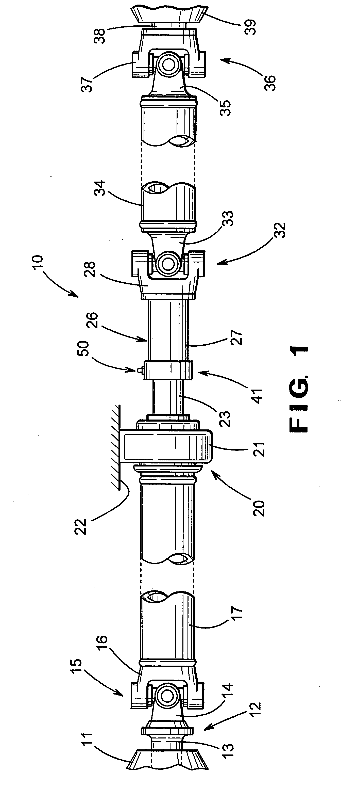
[0014]Referring now to the drawings, there is illustrated in FIG. 1 a drive train assembly, indicated generally at 10, for a vehicle which is adapted to transmit rotational power from an engine / transmission assembly 11 to a plurality of driven wheels (not shown). The engine / transmission assembly 11 is conventional in the art is and typically includes an externally splined output shaft (not shown) which is connected to a first slip yoke assembly, indicated generally at 12. The first slip yoke assembly 12 is conventional in the art and includes an internally splined tubular end portion 13 which slidably engages the externally splined output shaft of the engine / transmission assembly 11. As a result, the tubular end portion 13 of the first slip yoke assembly 12 is rotatably driven by the output shaft of the engine / transmission assembly 11, but is free to move axially relative thereto to a limited extent.

[0015]The first slip yoke assembly 12 further includes a yoke 14, which forms one pa...


PUM


Abstract

A slip joint includes a slip shaft having a plurality of axially extending grooves, and a slip yoke having a plurality of axially extending grooves. The slip yoke is in telescoping engagement with the slip shaft, and the grooves formed in the slip shaft are circumferentially aligned with the grooves formed in the slip yoke. A plurality of torque transmitting balls is disposed in the grooves. A helically shaped cage is positioned radially between the slip shaft and the slip yoke. The cage secures the balls to maintain the balls spaced apart from one another and within the grooves.

Description

BACKGROUND OF THE INVENTION[0001]This invention relates in general to the manufacture of slip joints, such as are commonly used in vehicle drive train systems, for transmitting rotational force or torque between axially movable components. In particular, this invention relates to an improved structure for a cage for maintaining the balls in a rolling ball spline type of slip joint in a spaced apart relationship.[0002]Drive train systems are widely used for transferring power from a power source to a driven mechanism. Frequently, the power source generates rotational power, and such rotational power is transferred from the power source to a rotatably driven mechanism. For example, in most land vehicles in use today, an engine / transmission assembly generates rotational power, and such rotational power is transferred from an output shaft of the engine / transmission assembly through a driveshaft assembly to an input shaft of an axle assembly so as to rotatably drive the wheels of the veh...

Claims


Application Information

Patent Timeline
Patent Type & Authority Patents(United States)
IPC IPC(8): F16C3/03F16C3/035F16C29/04F16C33/38F16D1/10F16D3/06F16D3/38
CPCF16C3/035F16C29/04F16C33/38F16D3/065F16D3/387F16D1/101Y10T403/7035
Inventor DA SILVA, JOSE P.
Owner DANA AUTOMOTIVE SYST GRP LLC
Why Eureka
Try Eureka