Optical device for viewing of cavernous and/or inaccessible spaces

an optical device and cavernous space technology, applied in the field of optical instruments adapted, can solve the problems of not being able to withstand sterilization not being able to adapt to many applications, etc., and achieves the effect of low bending force sensitivity, easy assembly and simple endoscope design

Inactive Publication Date: 2006-03-28
OPTISCOPE TECH LTD
View PDF11 Cites 14 Cited by
  • Summary
  • Abstract
  • Description
  • Claims
  • Application Information

AI Technical Summary

Benefits of technology

[0019]The present invention affords a simple design of an endoscope in comparison to many of those known in the art as it can operate with but a few optical elements, most of which are positioned at one of two locations i.e. near the distal end of the slender tube as part of the imaging system or near the proximal end as part of the telescopic system. Thus, the simple design of the endoscope of the present invention affords the device a number of considerable advantages including the device's relatively low sensitivity to bending forces and other mechanical loads that may be applied thereto during handling, when compared with relatively complicated endoscopic designs known in the art having many lenses and / or other optical elements, which have a tendency to render the endoscope optically inoperable even after slight bending, and often become damaged thereby. Furthermore, the endoscope of the present invention is easily assembled, especially because its limited number of image-forming optical components is located at few and specific locations of the device, specifically near its extremities.
[0020]In addition to the foregoing, the simple design of the present invention provides yet another advantage in the ability to thus produce a relatively inexpensive endoscope or other such device, which thereby also enables production of a completely disposable endoscope or of one having disposable parts, such as the rigid slender tube with its imaging system. Such an endoscope tube is, in fact, another aspect of the present invention.
[0021]The facility with which the endoscope or the endoscope tube of the present invention may be rendered sufficiently inexpensive to be disposable is a particularly beneficial feature in medical applications where instruments for introduction into the human body, for example, must often undergo sterilization.
[0022]Also, the simple design and assembly of the endoscope in accordance with the present invention enables its cost to be sufficiently minimized, particularly by choosing less expensive materials and methods for its manufacture, for example, that it may become economically feasible to dispose of the endoscope in its entirety after each use thereof. For example, the cost of the endoscope may be minimized by producing the imaging system, the telescopic system, the slender tube, as well as other parts of the endoscope body, from suitable plastic materials. In addition, the use of a ball lens in the imaging system, as mentioned above, for example, may be especially advantageous in this respect since, due to its simple geometry, the ball lens may be easily and inexpensively produced. Furthermore, due to its symmetry, the ball lens is easy to assemble, as its orientation is identical in any disposition.
[0023]Another example of a preferred manufacturing method includes production of the slender tube from a strip of metal sheeting which is blacked on one side by galvanic coating, paint, or other suitable material. The strip is then cold or hot drawn and welded to form the tube, with the blackened side constituting its inner surface to serve as a means, as known in the art, for preventing unwanted residual reflections of light from propagating through the tube and adversely affecting the image quality.

Problems solved by technology

However, when compared with rigid endoscopes, flexible endoscopes provide reduced image quality, are relatively expensive, and are not suitable for many applications.
They are also normally not adapted to withstand sterilization by an autoclave.
However, the delicate and complicated construction of reuseable endoscopes makes their absolute sterilization difficult to achieve.

Method used


Image

  • Optical device for viewing of cavernous and/or inaccessible spaces
  • Optical device for viewing of cavernous and/or inaccessible spaces
  • Optical device for viewing of cavernous and/or inaccessible spaces

Examples


Embodiment Construction

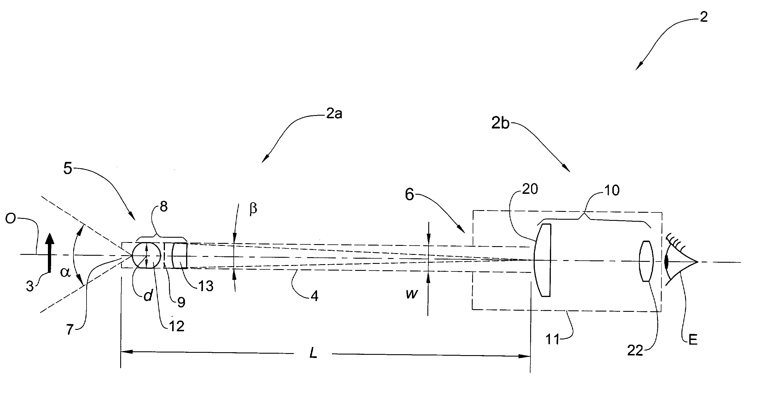
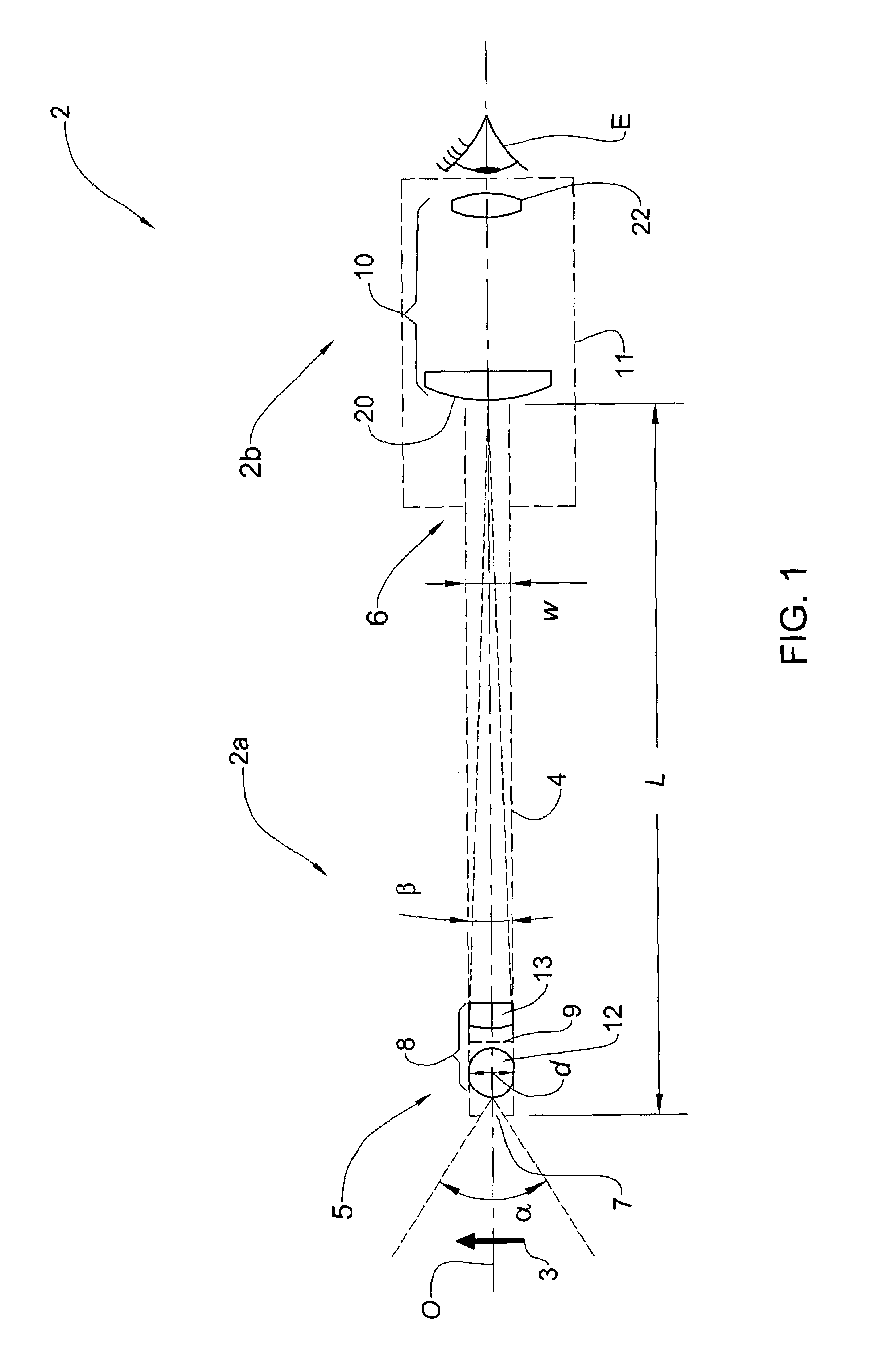
[0032]An endoscope 2 in accordance with the present invention is generally described below with reference to FIG. 1. The endoscope 2 is adapted for viewing, by a viewer's eye E or an image-receiving viewing device e.g. a CCD camera (not shown), an object 3, such as an interior of a body organ or a tumor, within a pre-determined range of working distances. The endoscope 2 comprises an imaging portion 2a and a viewing portion 2b arranged along a common optical axis O.

[0033]The imaging portion 2a includes a hollow rigid slender tube 4 with an imaging system 8 mounted therein. The slender tube 4 has a width w and a length L separating its distal end 5 and proximal end 6, the length L being considerably greater than the width w of the tube. The imaging system 8 is disposed within the tube 4 near its distal end 5 and is adapted to form an image of the object 3 on image plane 9 located adjacent to the imaging system 8. The imaging system 8 possesses such a wide viewing angle α, i.e. a shor...


PUM


Abstract

An optical device for viewing an object at a range of working distances. The device comprises a slender tube of a certain length and having a distal end and a proximal end. The device farther comprises an imaging system disposed at the distal end and having a wide viewing angle. The device also comprises a telescopic system associated with the proximal end and having a narrow viewing angle. The imaging system is designed to form an image of the object at an image plane located on the device's optical axis and within the tube closer to the distal end than to the proximal end. The telescopic system is designed to enable viewing of the image of the object. The device is especially adapted to function as an endoscope in medical applications and may be disposable.

Description

[0001]This application claims the benefit of provisional application Ser. No. 60 / 385,888, filed Jun. 6, 2002.FIELD OF THE INVENTION[0002]This invention relates to optical instruments adapted for viewing of cavernous and / or inaccessible spaces and which may be employed to view objects such as internal body organs and cavities thereof, as well as particular objects located in such organs, e.g. a tumor or a cyst. These optical instruments include endoscopes, otoscopes, laparoscopes, arthroscopes, bronchoscopes, laringoscopes, cystoscopes and other similar rigid endoscopic medical examination devices. Such optical instruments are not limited to medical use, however, and may be found in any of a variety of fields in which inspection as described above may be applicable, e.g. in mechanical applications, such as in the form of a borescope. More particularly, the invention relates to such optical instruments that are further designed to be disposable.BACKGROUND OF THE INVENTION[0003]Various...

Claims


Application Information

Patent Timeline
Patent Type & Authority Patents(United States)
IPC IPC(8): A61B1/00G02B23/26A61B1/002A61B1/313G02B13/22G02B13/24
CPCA61B1/00096A61B1/00195G02B13/22A61B1/3132A61B1/002
Inventor ALEKSEENKO, SERGEI V.EVSEEV, ALEKSEY R.BELOUSOV, PETER Y.BELOUSOV, ANDREY P.DIAMANT, LEVDUBNISTCHEV, YURI N.MARKOVICH, DMITRIY M.MELEDIN, VLADIMIR G.STAROHA, ALEKSANDER V.
Owner OPTISCOPE TECH LTD
Why Eureka
Try Eureka