Eureka AIR delivers breakthrough ideas for toughest innovation challenges, trusted by R&D personnel around the world.

Water treatment method and water treatment device

Inactive Publication Date: 2006-03-28
HITACHI LTD
View PDF10 Cites 31 Cited by
  • Summary
  • Abstract
  • Description
  • Claims
  • Application Information

AI Technical Summary

Benefits of technology

[0021]Embodiments of the present invention provide a water treatment method and water treatment device whereby automatic tracking of the frequency of the ultrasonic waves such that optimal cavitation is generated, and automatic control of amplitude can be achieved and whereby notification of abnormality can be performed in cases such as where the change of resonant frequency produced by erosion of the device itself exceeds the operating range, or where water is absent and, furthermore, whereby a warning can be generated in cases

Problems solved by technology

When water treatment devices described above are actually employed, they are subject to the problem that the frequency of the ultrasonic waves that is optimum for generation of cavitation fluctuates depending on the effect of parameters such as water temperature, flow rate and impurities, so that it is difficult for optimal cavitation to be generated.
In addition, if the devices described above are employed in a condition in which water is absent, the amplitude becomes abnormally large, giving rise to the problem that the device is in danger of being destroyed and the further problem that the device itself may be exfoliated by the cavitation generated by the device, causing changes in the resonant frequency.
When the bubbles produced by cavitation collapse, a shock of 1000 to 5000 atmospheres is generated in a short period in a minute region; this has an extremely large destructive power.
With this device, the acoustic pressure that was applied and the mechanism of bubble generation were not elucidated.
Moreover, there were the following problems.(1) The region where cavitation bubbles were generated was small and it was difficult to produce cavitation in the entire body of liquid.(2) If cavitation was produced in the entire body of liquid, a large liquid flow rate could not be achieved.(3) The size of the cavitation bubbles was difficult to control.(4) Erosion of the tip of the horn occurred due to cavitational erosion, producing particles which became mixed with the liquid.
There have been instances of deaths caused by pneumonia due to Legionella bacteria proliferating in water at hot springs and the social problem has also risen of diarrhea epidemics due to cryptosporidium bacteria present in mains water supplies.
However, in the case of a circulatory hot-water bath, there are respectively the following problems.(1) Chlorine: this causes a change of the pH value and produces a change of the water quality.
It gives an unpleasant feeling to the bather, since a smell of chlorine is generated.
The chlorine is consumed simply by persons taking a bath so that no residual chlorine is left; managing the amount of chlorine with each bath is therefore a troublesome task.
Furthermore, since high ozone concentrations are toxic to the human body, de-ozonization treatment using activated carbon or the like is required.(4) Membrane filtration: this is undesirable as a filter for a bath, since bathing agents and the like are removed.
Also, blockage of the pores occurs.

Method used


Image

  • Water treatment method and water treatment device
  • Water treatment method and water treatment device
  • Water treatment method and water treatment device

Examples


Embodiment Construction

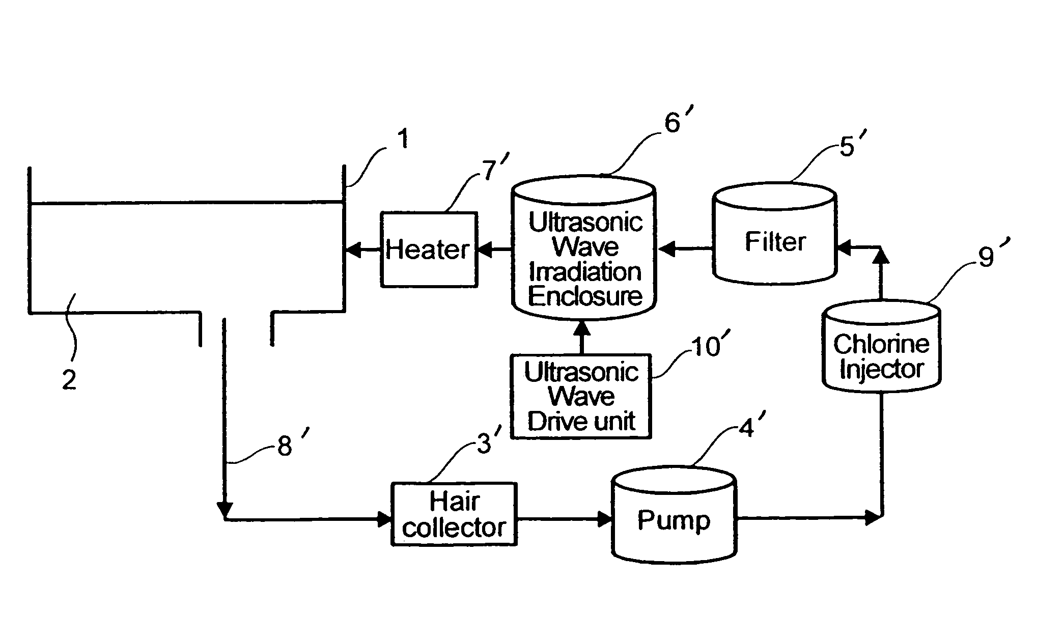
[0050]Embodiments of the water treatment methods and water treatment devices according to the present invention are described below in detail with reference to the drawings.

Ultrasonic Device

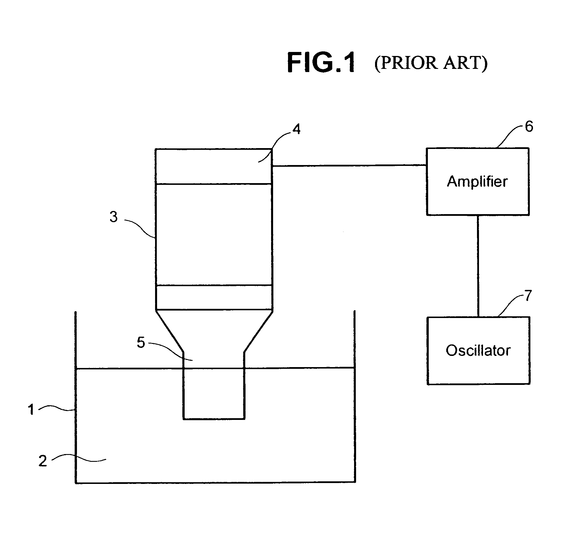
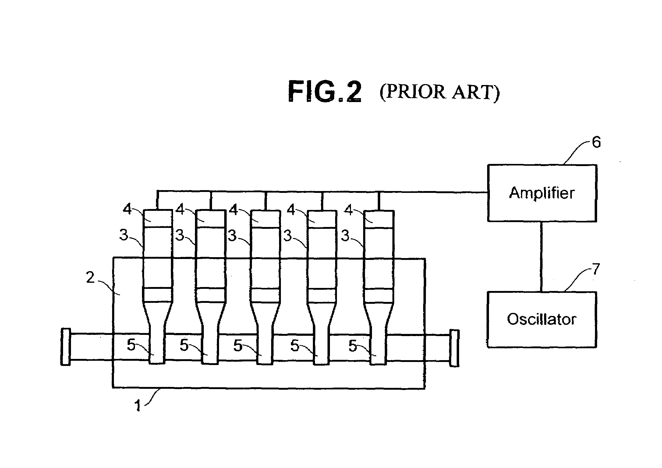
[0051]FIG. 3 is a diagram of an ultrasonic device constituting an embodiment of the present invention. High frequency waves from an oscillator 7 pass through an amplifier 6 and are applied to a vibration source 8 of a vibrator 3′. As this vibration source 8, a magnetostriction or piezoelectric element may be selected. The vibration from the vibration source 8 is directed into the liquid 2 in the form of sound waves from the tip 9 of horn 5′. The liquid 2 flows into an ultrasonic device 100A from an inlet port 10 provided with a flange and flows out from an outlet port 11 provided with a flange. The enclosure 1′ of the ultrasonic device 100A is divided into an inlet chamber 14 and outlet chamber 15 by a partition 12, these being linked through a non-return hole 13 provided in the partition 12. The...


PUM


Abstract

Embodiments of the invention provide a water treatment method and water treatment device capable of automatically tracking the frequency of ultrasonic waves and automatically controlling their amplitude such that optimal cavitation is generated. In one embodiment, a water treatment method of sterilizing water containing microbes comprises supplying ultrasonic vibration to the water to be treated by driving and controlling a transducer of a sterilization cell using a signal; detecting an amplitude of the transducer and a frequency of the signal applied to the transducer; and controlling the amplitude and a vibration frequency of the transducer to target values in accordance with the detected transducer amplitude and the detected signal frequency.

Description

CROSS-REFERENCES TO RELATED APPLICATIONS[0001]This application relates to and claims priority from Japanese Patent Application Nos. 2003-069051, filed on Mar. 14, 2003; 2003-078241, filed on Mar. 20, 2003; and 2003-059307, filed on Mar. 6, 2003. The entire disclosures of these applications are incorporated herein by reference.BACKGROUND OF THE INVENTION[0002]The present invention relates to water treatment methods and devices and, more particularly, to a water treatment method and water treatment device suitable for use for sterilizing microbes in drinking water, a circulatory bath, or the like.[0003]It is previously known that intense ultrasonic waves have a sterilizing effect and sterilizing devices for sterilizing bacteria that cause problems in drinking water or circulatory baths or the like are being developed using the sterilizing effect of such ultrasonic waves. Examples of water treatment devices constituting sterilizing devices of this type are described in Laid-open Japane...

Claims


Application Information

Patent Timeline
IPC IPC(8): C02F1/36B06B1/02C02F1/00C02F1/76
CPCB06B1/0253C02F1/36B06B2201/70C02F2103/42C02F1/76C02F1/008
Inventor KURIHARA, MASAHIROTAKEI, KAZUOHASHIBA, KUNIOKATAKURA, KAGEYOSHI
Owner HITACHI LTD
Why Eureka
Eureka Blog
Learn More