Imaging millimeter wave radar system

a radar system and millimeter wave technology, applied in the direction of linear waveguide fed arrays, instruments, antennas, etc., can solve the problems of poor angular resolution of these systems, slow for many hazard avoidance applications, and especially for helicopters

Inactive Publication Date: 2006-03-28
TREX ENTERPRISES CORP
View PDF12 Cites 128 Cited by
  • Summary
  • Abstract
  • Description
  • Claims
  • Application Information

AI Technical Summary

Problems solved by technology

In general angular resolution with these systems is poor and typically they are too slow for many hazard avoidance applications.
Aircraft are typically equipped with radar devices for detection of hazards; however, at the frequencies of most radar very thin objects such as po

Method used


Image

  • Imaging millimeter wave radar system
  • Imaging millimeter wave radar system
  • Imaging millimeter wave radar system

Examples


first preferred embodiment

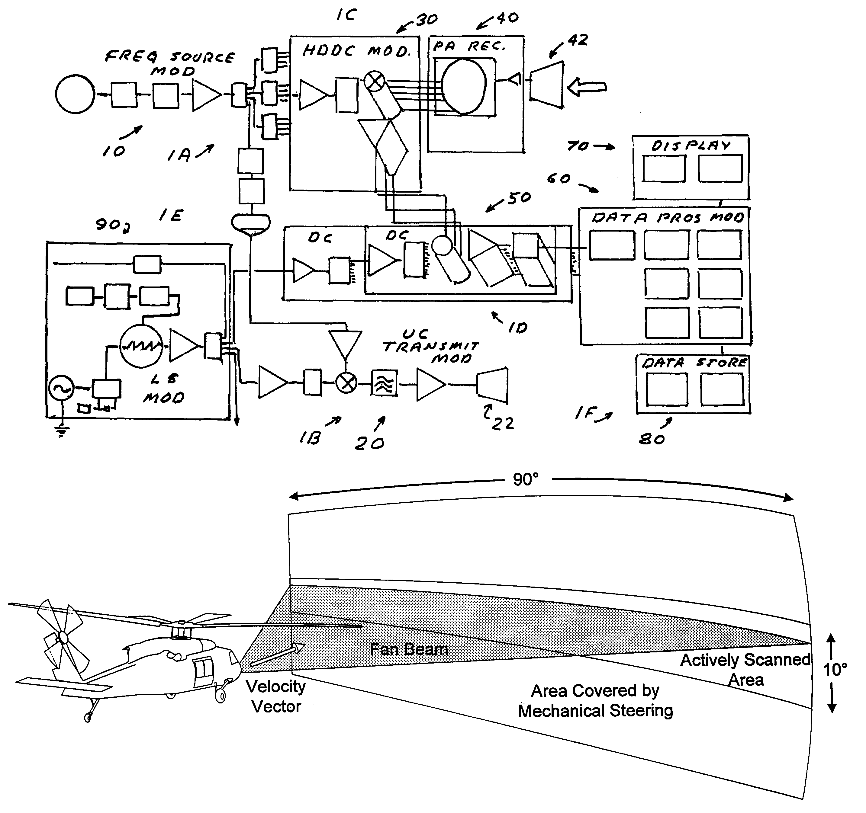
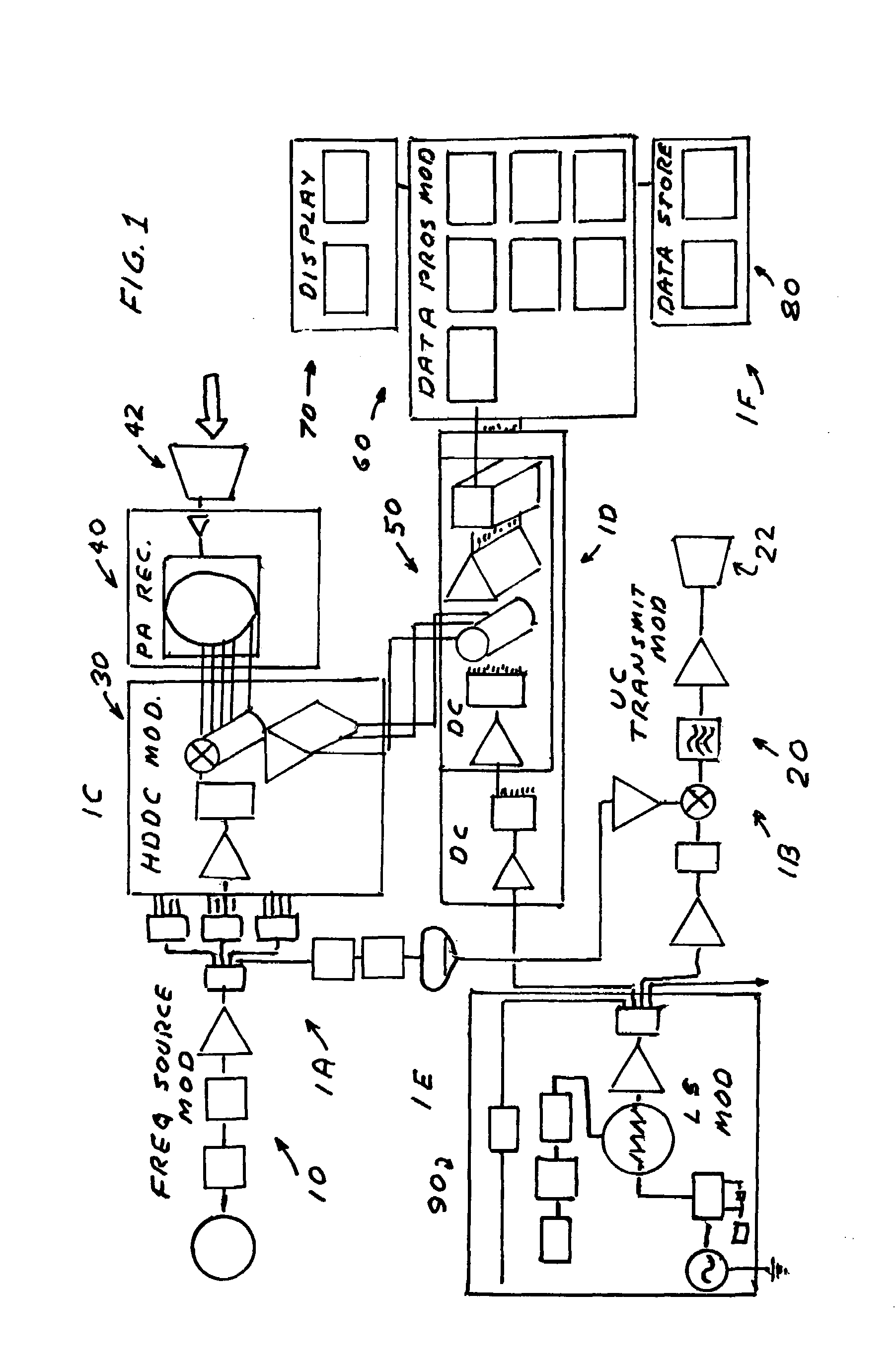
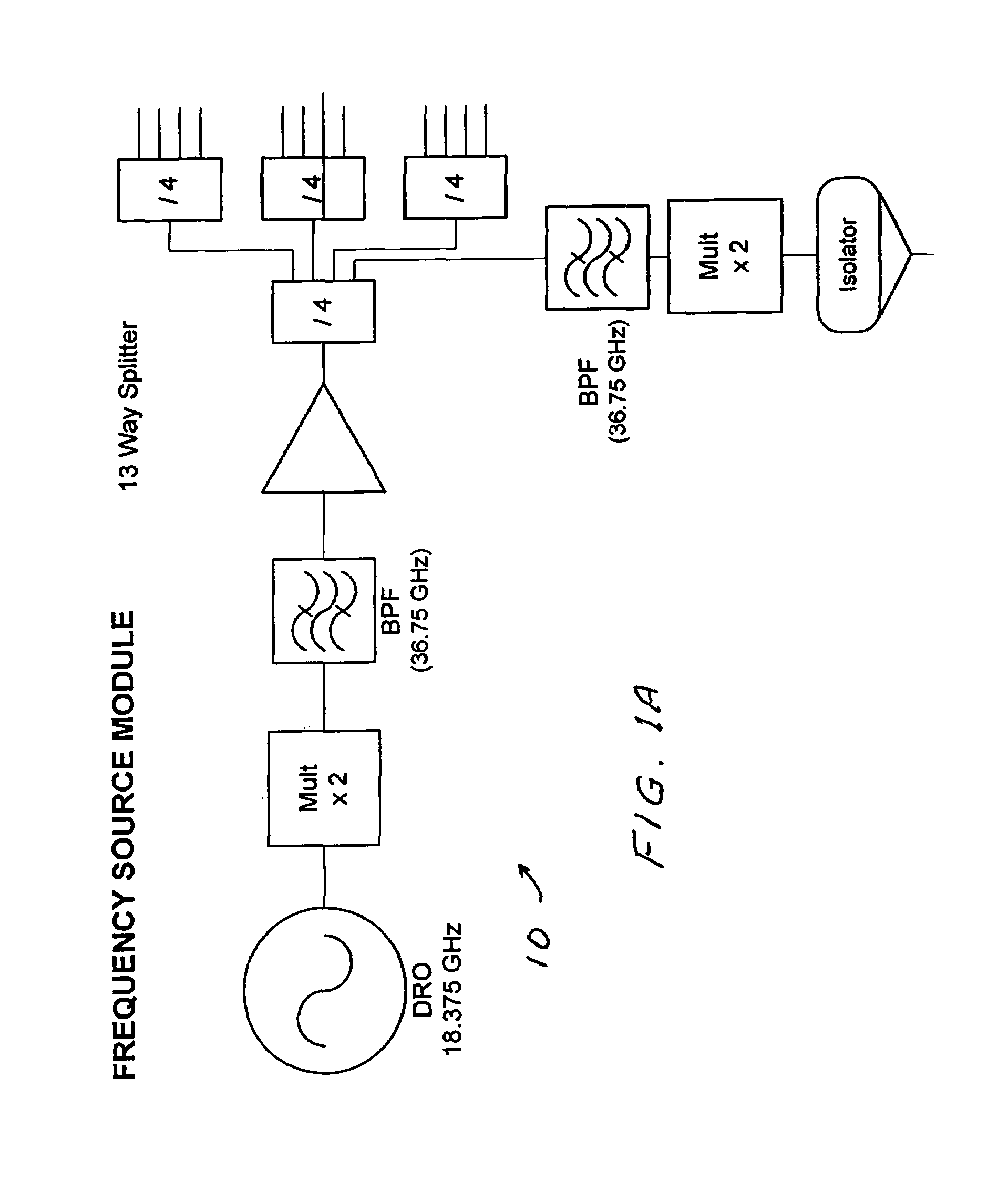
[0018]A first preferred embodiment of the present invention is described in FIGS. 1 through 5D. It is an active illuminator married with a passive millimeter wave camera. This embodiment is a three dimensional W-band frequency modulated continuous wave (FMCW) active imaging radar system. It includes a frequency-scanned, phased-array receive antenna; a single-element, frequency-scanned transmit antenna and a 192-tap Rotman lens. The system employs a linear frequency modulated chirp radio frequency waveform sweeping from 78 to 81 GHz in 16.7 msec (60 Hz scan frequency) for a scan rate of 180 GHz / sec. The system provides the following capabilities:[0019]1. Operational range: 30 m to 1000 m.[0020]2. Hazard detection range: >500 m (⅜-inch wire @ 60° oblique angle).[0021]3. Field of view: 90° azimuth×10° elevation.[0022]4. Range resolution: 5 m.[0023]5. Cross-range spatial resolution: 9 mrad (5°) @ boresight.[0024]6. Transmitter frequency: chirped, 78 to 81 GHz.[0025]7. Transmitter power:...

second preferred embodiment

[0054]A second preferred embodiment of the present invention is useful for imaging at close distances with very poor visibility such as heavy fog or dust conditions. One such situation arises when attempting to land a helicopter in on a sandy or dusty field. The major changes in the radar's operational requirements relative to the first embodiment are those of significantly decreased operating range and significantly increased range resolution. Shorter ranges and larger return cross-sections lead to simplifications of the transmitter design, particularly in eliminating the need for a high-power millimeter-wave (MMW) amplifier, and of the receiver design, in eliminating the need for a low-noise MMW phased array receiver. On the other hand, the shorter operational range, as well as the need for greatly increased range resolution, limits the size of the antenna aperture that can be utilized and thus restricts the angular resolution of the radar. By returning to first principles of the ...


PUM


Abstract

An imaging millimeter wave radar system. The system includes a millimeter wave transmitter transmitting a frequency scanned millimeter beam that is narrow in the scanned direction and wide in a direction perpendicular to the scanned direction. The system includes a receive antenna and a Rotman type lens for forming a one-dimensional image in the perpendicular direction of targets in the antennas field of view based on millimeter wave radiation reflected from the targets. A computer creates a two dimensional image based on the scanning direction of the transmit beam of the transmit antenna and the one dimensional image from the receive antenna. Distance to the target is determined based on difference in frequency of the transmit signal and the receive signal. Thus, a three dimensional view of the systems field of view is determined by the system. This view can be displayed on a monitor using color to represent target distance. In a preferred embodiment the scanned direction is the vertical direction and the receive antenna forms a horizontal image from signals reflected from targets in the field of view. In this preferred embodiment the transmit antenna is a variable frequency millimeter wave single channel wave guide antenna operating in the 78 GHz to 81 Ghz spectral range to produce a scanning range of 10 degrees and a scanning rate of 60 Hz. The receive antenna is a multi-channel (176 channels) strip-line antenna also operating in the 78 GHz to 81 GHz spectral range, which with the Rotman lens, provides 192 horizontal pixel resolution.

Description

[0001]The present invention relates to radar systems and in particular to wave imaging radar systems.BACKGROUND OF THE INVENTION[0002]Imaging systems operating at millimeter wavelengths (1 cm to 1 mm; 30 GHz to 300 GHz) are known. These systems can be important because light at these wavelengths is not completely attenuated by substantial distances of fog or smoke, as is visible light. Light at millimeter wavelengths will also penetrate clothing and significant thickness of materials such as dry wood and wallboard. These millimeter wave imaging systems have therefore been proposed for aircraft to improve visibility through fog and for security applications for detection of concealed weapons and the like.Passive Millimeter Wave Imaging[0003]Passive millimeter wave imaging systems are described in U.S. Pat. Nos. 5,121,124 and 5,365,237 that are assigned to Applicant's employer. The systems described in those patents utilize antennas in which the direction of collected millimeter wave ...

Claims


Application Information

Patent Timeline
IPC IPC(8): G01S13/89G01S13/93G01S13/933
CPCG01S7/03G01S13/89H01Q25/008H01Q21/005G01S13/9303G01S2013/0245G01S13/933
Inventor LOUBERG, JOHNKOLINKO, VLADIMIRWOODBRIDGE, ERICSAUNDERS, ROBERT C.
Owner TREX ENTERPRISES CORP
Why Eureka
Try Eureka