Light beam deflector

a technology of light beam and deflector, which is applied in the direction of optics, instruments, optics, etc., can solve the problems of limited value, limited operating range, and complicated control signals of two axes tilting mirror deflectors, and achieve the effect of simplifying the deflection of light beams

Inactive Publication Date: 2006-03-28
HYPERBOLOID CORP
View PDF8 Cites 10 Cited by
  • Summary
  • Abstract
  • Description
  • Claims
  • Application Information

AI Technical Summary

Benefits of technology

[0015]According to a third aspect of the present invention, a method for controllably deflecting a light beam is provided. The method allows for simplified deflection of the light beam by utilizing a light deflector that maintains a constant distance between the light source and a mirror, thereby eliminating one or more variables required to generate a control signal for positioning and / or moving a mirror to controllably deflect a light beam. In this regard, the mirror may be tilted to an initial tilt angle about a first axis that is substantially aligned with the reflective surface on that mirror. Furthermore, the mirror may be rotated to an initial angular orientation about a second axis that is transverse and typically perpendicular to the first axis such that the mirror has a desired initial orientation. That is, the mirror may initially be tilted to deflect a light beam from a light source to a first known position. Once the mirror is set to its initial position, the mirror may be moved about one or both the first and second axes to controllably deflect the light beam from the first position to the second position.

Problems solved by technology

Each of the above deflectors (i.e., oscillating and two axes tilting), while being well suited for some applications, are often of limited value in applications requiring multiple degrees of mirror freedom for directing a light beam in complex patterns.
For example, oscillating deflectors while being well suited for line by line scanning application often have a limited operating range as well as a mirror fixed in a single plane.
Furthermore, two axes tilting mirror deflectors tend to be mechanically intricate and often require complex control signals in order to adjust the deflector's mirror to a desired orientation.
In this regard, these deflectors are of limited value in scanning and graphic applications where it is desirable to rapidly scan a beam across a surface in a controlled manner.
That is, periodic, harmonic or other complex light deflection patterns may require unduly complex control signals that require expanded processing and control systems and / or require feedback to properly direct a deflected light beam to a point in space.
Furthermore, deflection about two axes often results in translating the mirror relative to a fixed reference point.
Accordingly, this relative movement between the mirror and the light source may change the distance and / or angle between the light source and mirror introducing additional complexities in generation of control signals for use in directing a light beam in a desired manner.

Method used


Image

  • Light beam deflector
  • Light beam deflector
  • Light beam deflector

Examples


Embodiment Construction

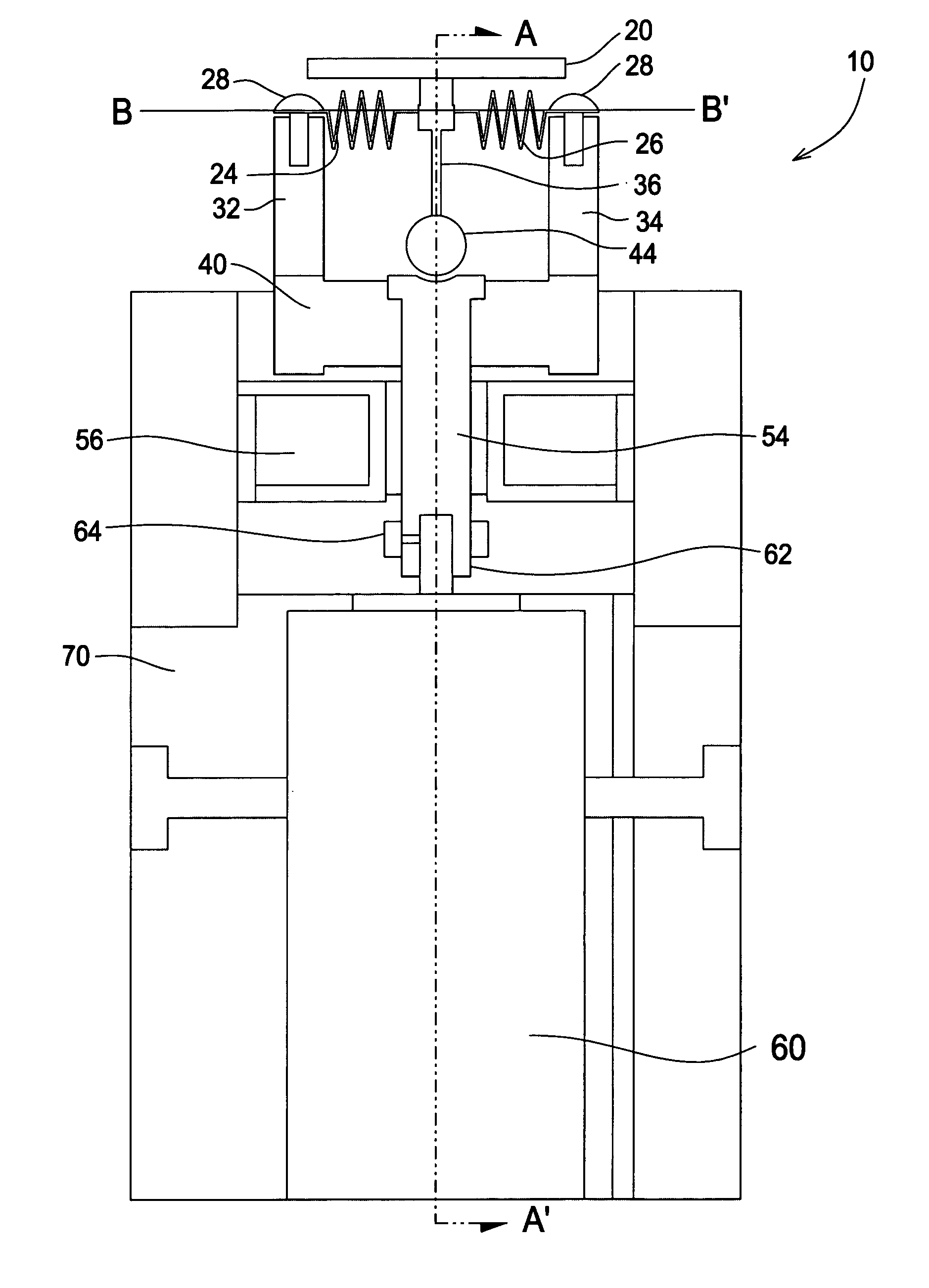
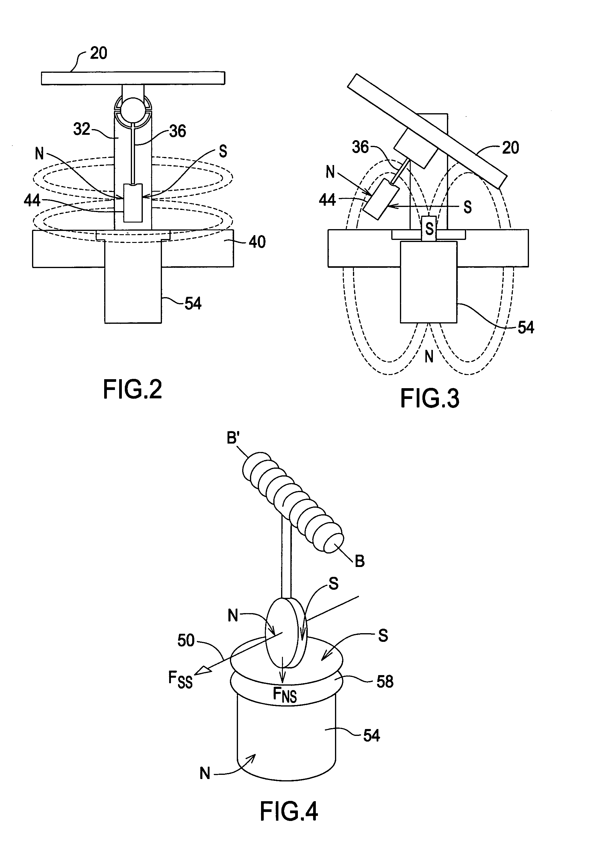
[0022]The present invention is directed to a light beam deflector utilized to controllably deflect a concentrated light beam (e.g., laser and / or multi-wavelength concentrated light beams). The deflector is applicable for a variety of light beam deflection applications including, without limitation, compact beam scanning applications (e.g., for reading bar codes), controlled movement of medical laser devices, light projection applications such as light shows, as well as for use in creating optical connections. In this regard, the deflector utilizes a mirror that may be controllably tilted about an axis of oscillation that may be oriented in any angular position (0 to 2π) about an axis of rotation perpendicular to the axis of oscillation. Accordingly, this allows the mirror to tilt in any one of an infinite number of planes passing through the point of intersection of the axes. Furthermore, the mirror may be oscillated between first and second tilt angles in any plane coinciding with ...


PUM


Abstract

The present invention relates to a device for use in deflecting a concentrated light beam in two coordinates, for example, of a polar coordinate system. In this regard, the device utilizes a mirror that may be controllably tilted or oscillated about an axis of oscillation and that may also be rotated to any angular position (0 to 2π) about an axis of rotation. In this regard, the mirror may be tilted in any one of a number of planes passing through the intersection point of the axis of oscillation and axis of rotation. Furthermore, the mirror may be oscillated between first and second angular positions or tilted to a fixed angle relative the axis of oscillation, in conjunction with controlled movement around the axis of rotation. In this regard, a device is provided wherein the mirror has multiple degrees of freedom allowing for a plurality of beam deflection applications.

Description

FIELD OF THE INVENTION[0001]The present invention relates to a device for deflecting a light beam in a controllable manner. In particular, the present invention relates to a device for use in deflecting a concentrated light beam in two coordinates, for example, of a polar coordinate system.BACKGROUND[0002]In many applications, it is desirable to controllably deflect concentrated beams of electromagnetic energy (i.e., concentrated light beams) that originate from a fixed or moving light beam source. A short list of such applications includes scanning pictures onto video monitors, scanning information from bar codes, performing medical procedures, creating projected visual displays, e.g., for light shows, as well as for use in creating optical connections. Depending upon the specific application, it may be desirable to deflect concentrated light beams of multiple wavelength (polychromatic) visible light, monochromatic light (i.e., lasers) as well as non-visible light (e.g., ultraviole...

Claims


Application Information

Patent Timeline
Patent Type & Authority Patents(United States)
IPC IPC(8): G02B26/08
CPCG02B26/0833G02B26/085
Inventor SHPIZEL, MATVEY B.SPEKTOR, BORIS I.
Owner HYPERBOLOID CORP
Why Eureka
Try Eureka