Method and apparatus for indirect bonding of orthodontic appliances

Active Publication Date: 2006-04-04
3M INNOVATIVE PROPERTIES CO
View PDF21 Cites 158 Cited by
  • Summary
  • Abstract
  • Description
  • Claims
  • Application Information

AI Technical Summary

Benefits of technology

[0024]The present invention also is directed toward a number of improvements for indirect transfer apparatus, as will be described in more detail below. Examples of such improvements include structure for facilitating the application of uniform

Problems solved by technology

If, for example, a bracket is attached to the tooth at a location that is too close to the occlusal or outer tip of the tooth, the orthodontist using a straight-wire technique will likely find that the tooth in its final position is unduly intruded.
For example, access to surfaces of malposed teeth may be difficult.
In some instances, and particularly in connection with posterior teeth, the practitioner may have difficulty seeing the precise position of the bracket relative to the tooth surface.
Additionally, the appli

Method used


Image

  • Method and apparatus for indirect bonding of orthodontic appliances
  • Method and apparatus for indirect bonding of orthodontic appliances
  • Method and apparatus for indirect bonding of orthodontic appliances

Examples


Embodiment Construction

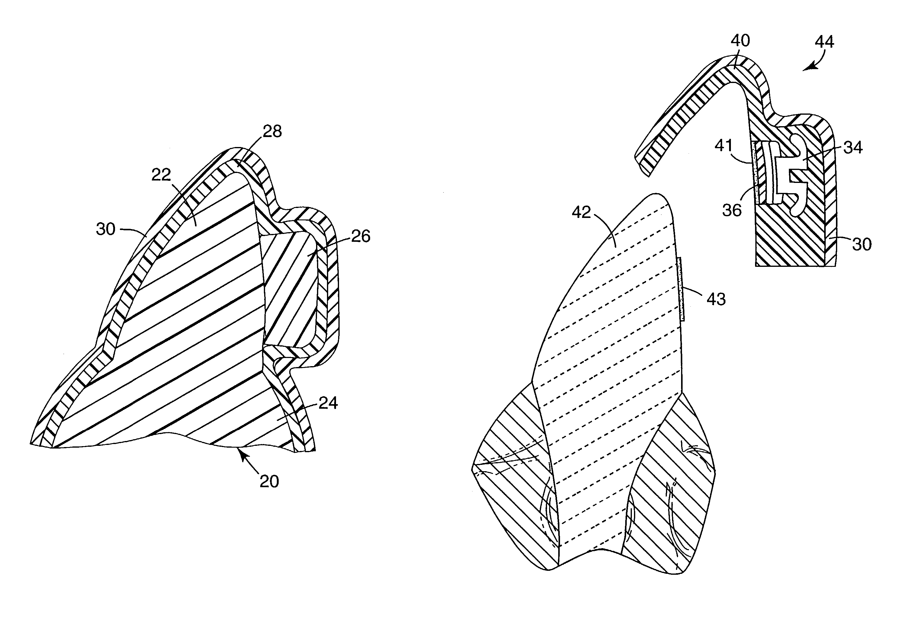
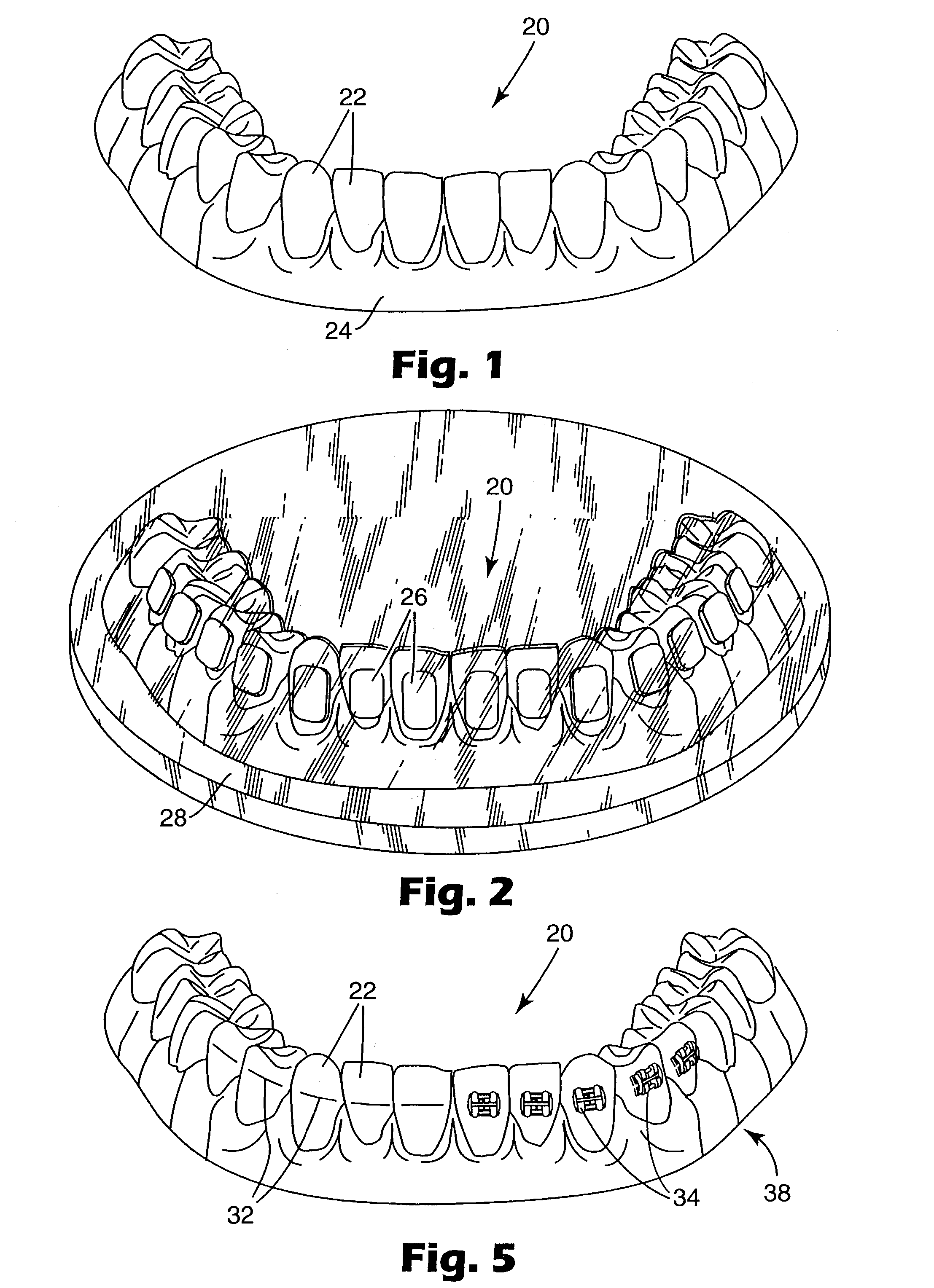
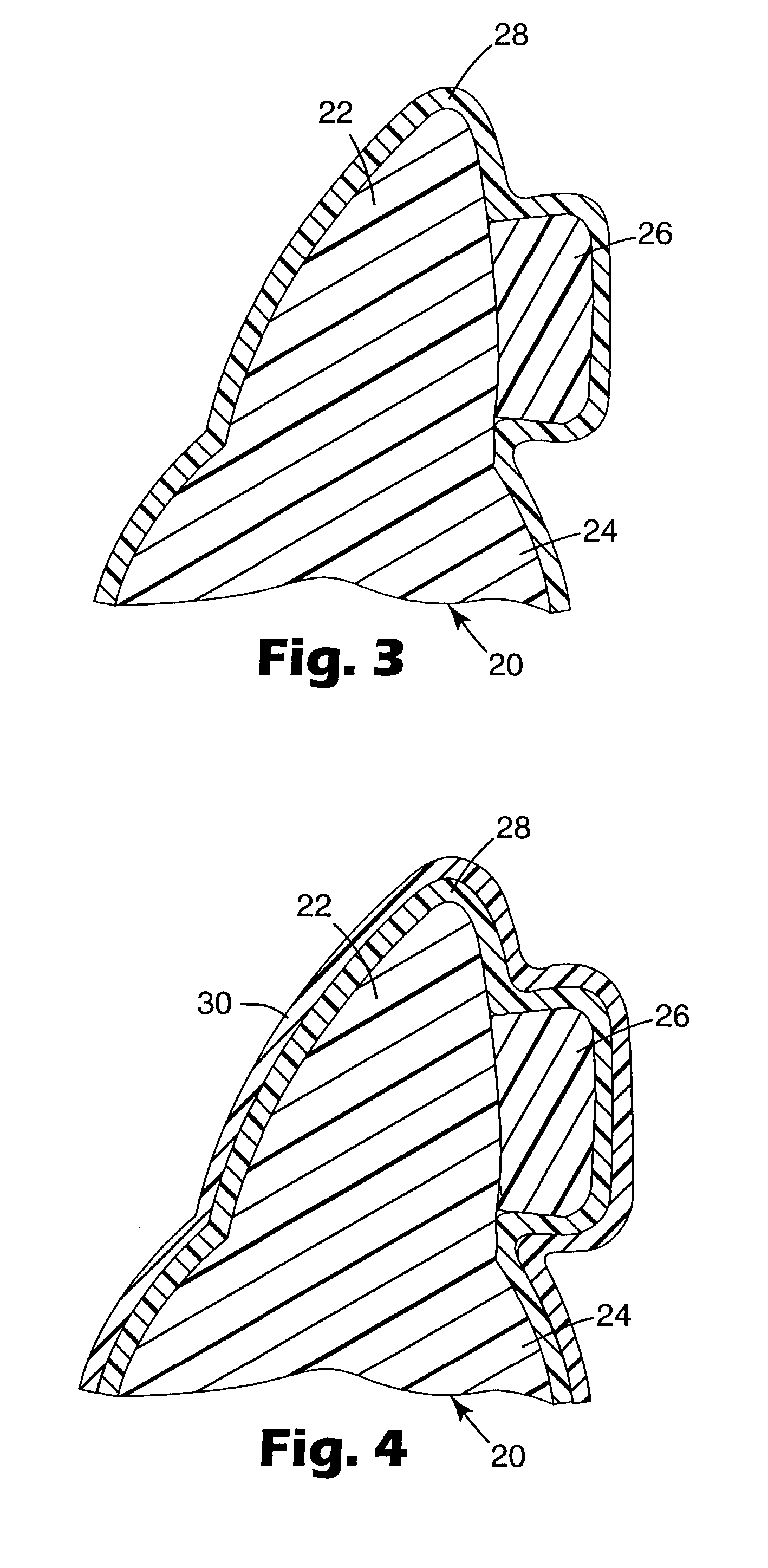
[0045]A method for indirect bonding of one or more orthodontic appliances in accordance with one aspect of the present invention will first be described. FIG. 1 illustrates a replica 20 of a portion of a dental arch of an orthodontic patient. For exemplary purposes, the replica 20 represents the patient's lower dental arch. However, a replica of a patient's upper dental arch may be provided as an addition to or as an alternative to the lower dental arch replica as shown. As a further option, the replica 20 may represent only a portion of a dental arch, such as a quadrant of an arch or only one or two teeth of a dental arch. In the example illustrated, the replica 20 includes a number of replica teeth 22, corresponding to each tooth of the patient's lower dental arch.

[0046]Optionally, the replica 20 is made by first taking an impression of the patient's lower dental arch, using care to avoid undue distortion. Optionally, an alginate impression material is used such as Unijel II algin...


PUM

PropertyMeasurementUnit
Pressureaaaaaaaaaa
Viscosityaaaaaaaaaa
Photocurableaaaaaaaaaa

Abstract

An indirect bonding apparatus is made by initially placing spacer material over a replica of the patient's tooth structure. A tray is then formed over the spacer material and hardened. Next, the spacer material is removed from the tooth replica and orthodontic appliances are placed on the replica at desired locations. A matrix material is placed between the tray and the replica and allowed to harden. Optionally, the apparatus includes features for facilitating removal of the transfer apparatus after the bonding procedure has been completed, and features for applying firm, uniform pressure to the appliances during the bonding procedure. Other aspects of indirect bonding are also described.

Description

BACKGROUND OF THE INVENTION[0001]1. Field of the Invention[0002]This invention relates to methods and apparatus for bonding orthodontic appliances such as brackets to a patient's teeth. The present invention facilitates precise positioning of the appliances in predetermined locations on the teeth and helps to minimize the amount of the patient's time that is spent in the orthodontic operatory.[0003]2. Description of the Related Art[0004]Orthodontic treatment involves movement of malpositioned teeth to desired locations in the oral cavity. Orthodontic treatment can improve the patient's facial appearance, especially in instances where the teeth are noticeably crooked or where the jaws are out of alignment with each other. Orthodontic treatment can also enhance the function of the teeth by providing better occlusion while eating.[0005]One common type of orthodontic treatment involves the use of tiny, slotted appliances known as brackets. The brackets are fixed to the patient's teeth a...

Claims


Application Information

Patent Timeline
IPC IPC(8): B21F43/00A61G15/00A61C7/14
CPCA61C7/146Y10T29/49567Y10T29/4998Y10T29/49568B33Y80/00
Inventor CLEARY, JAMES D.CINADER, DAVID K.PUTTLER, OLIVER L.SANKER, JOHN E.
Owner 3M INNOVATIVE PROPERTIES CO
Why Eureka
Try Eureka