Reverse molded plant-on panel component, method of manufacture, and method of decorating a door therewith

a technology of reverse molding and plant-on-panel, which is applied in the field of reverse molding, plant-on-panel decorative panel components, can solve the problems of difficult reverse molding, difficult to reverse mold and emboss deep draws into fiberboard panels, and high cost of historic treatment of real wood wainscots, etc., and achieves excellent transfer of mold detail and high density. , the effect of not visible fiber fractur

Inactive Publication Date: 2006-04-04
MASONITE CORP
View PDF11 Cites 35 Cited by
  • Summary
  • Abstract
  • Description
  • Claims
  • Application Information

AI Technical Summary

Benefits of technology

[0015]The present invention is directed to a reverse molded fiberboard panel; a wainscot kit comprising a plurality of differently sized reverse molded panels, and a planar finishing or spacer panel, adapted to completely cover any size wall between a wall base board and a wall chair rail; and a method of reverse molding a loose cellulosic mat, in a single pressing step, to provide one or more relatively high density, raised panels without requiring preliminary pressing, or other

Problems solved by technology

The prior art discloses that it is difficult to reverse mold and to emboss deep draws into a fiberboard panel due to stretching and breaking of the fibers.
A reverse molded fiberboard is stretched more on its visible outer surface than on its interior surface (i.e. the surface in contact with a raised mold surface) making reverse molding much more difficult when attempting to provide sharp, crisp design detail in a raised panel that simulates natural wood millwork.
Historic treatments of real wood wainscot are well established and very expensive.
Beyond the multiple piece millwork of real wood, some gypsum and polymeric materials have been fabricated into wainscot panels, but are marginally commercially acceptable, partly because they do not have the feel or look of natural wood.
However, this requires that the existing door be completely replaced.
Again, the new molded door or paneling may not have the proper dimensions for simple replacement.
For example, the dimensions of kitchen cabinets may be such that replac

Method used


Image

  • Reverse molded plant-on panel component, method of manufacture, and method of decorating a door therewith
  • Reverse molded plant-on panel component, method of manufacture, and method of decorating a door therewith
  • Reverse molded plant-on panel component, method of manufacture, and method of decorating a door therewith

Examples


first embodiment

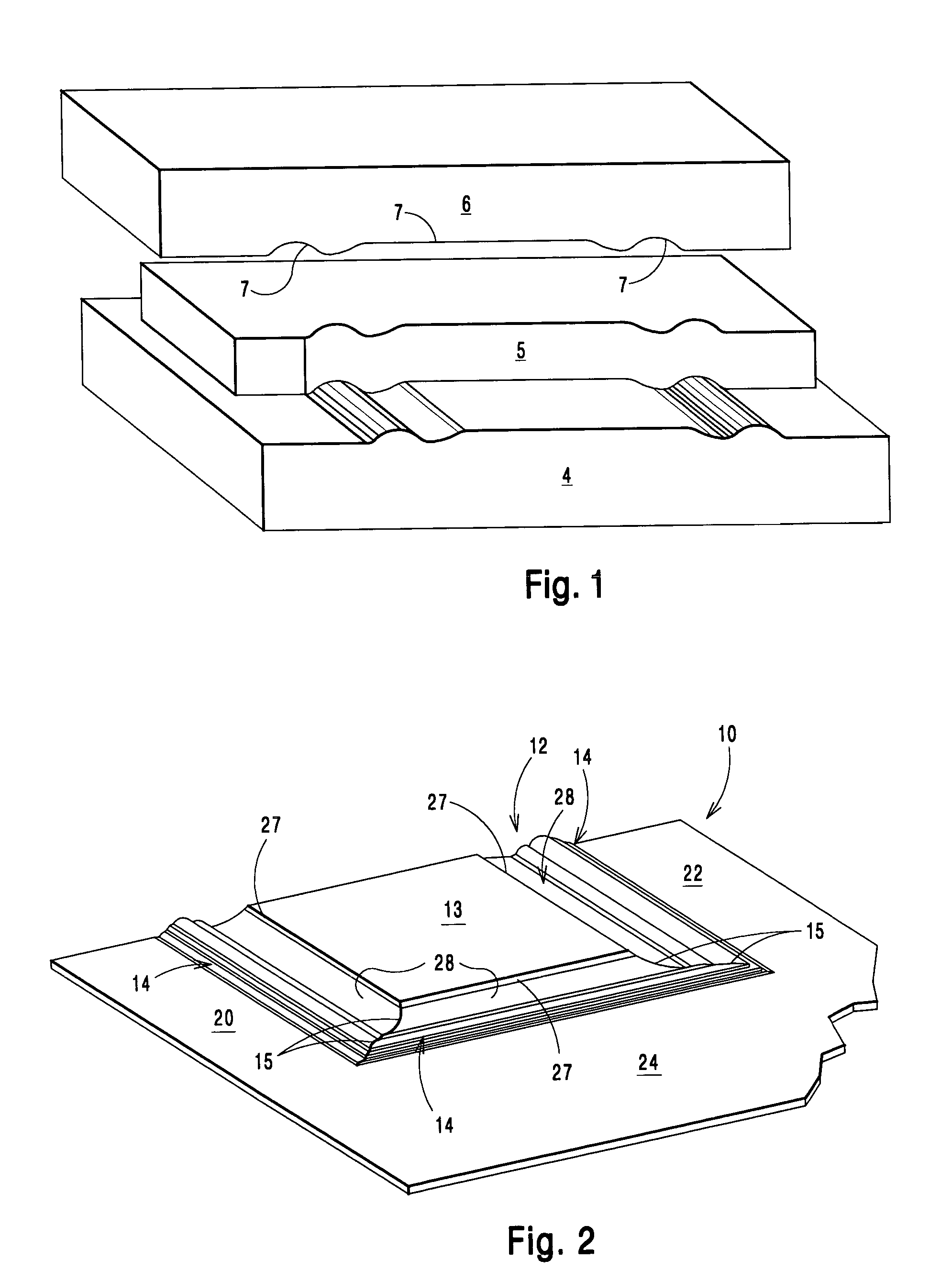
[0051]In the present invention, molded wood composite articles are molded in the form of wainscot paneling to be adhered to a planar interior wall between a wall base board and a wall chair rail, to simulate solid, natural wood wainscot millwork, as shown in FIG. 2. It should be understood, however, that the principles of the present invention are applicable to other molded articles, such as exterior and interior doors or door skins, cabinet and furniture door facings, furniture components, garage door skins, decorative wall paneling, wardrobe door facings, decorative hardboard, and other such molded, wood composite articles having one or more reverse-molded raised millwork designs adjacent to a planar surface portion of the molded article.

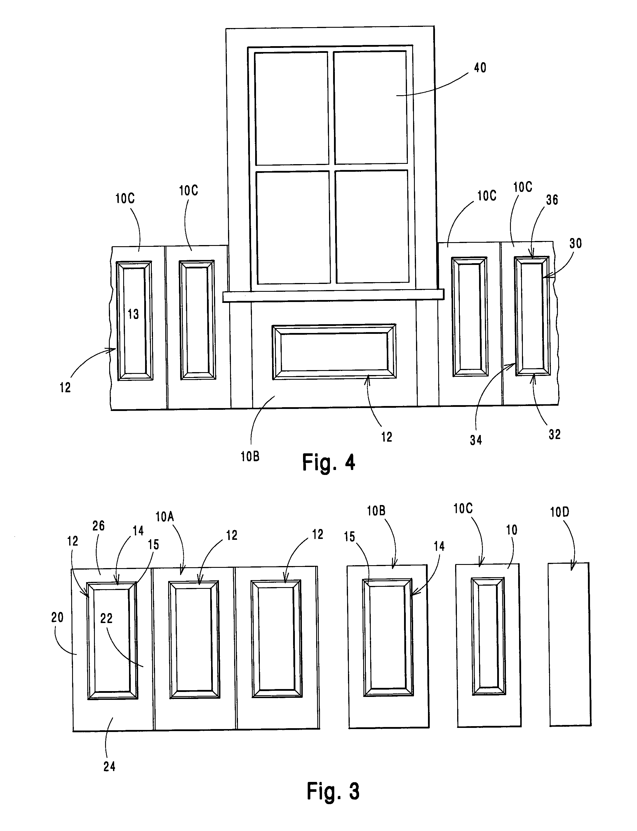
[0052]The dimensions of the reverse molded composite articles of the first embodiment preferably varies from 5 inches to 96 inches in width and from 12 inches to 60 inches or even 96 inches in height. Preferably, the articles of the present invent...

second embodiment

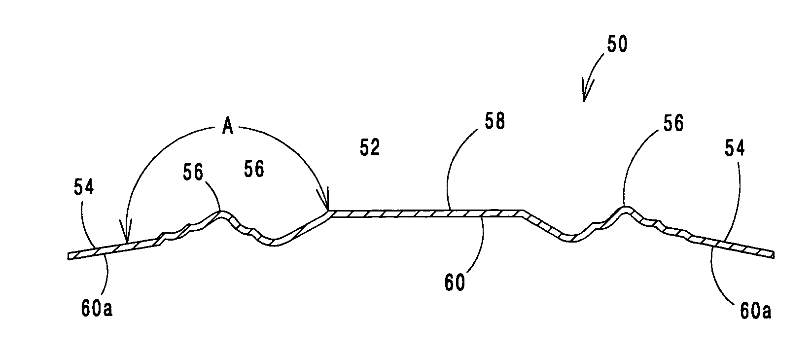
[0063]As best shown in FIG. 8, the present invention provides a reverse molded, plant-on decorative panel component 50, which may be adhesively secured to a planar surface, and is tensioned to the planar surface when secured thereon. Plant-on panel component 50 comprises a panel portion 52 lying on a first plane, a skirt portion 54, and a contoured portion 56. Preferably, panel portion 52 is rectangular. However, it should be understood that panel portion 52 may be formed to have any shape, pursuant to consumer preference. Panel portion 52 lies on a plane that is coplanar with a plane extending between the uppermost parts of contoured portion 56. Contoured portion 56 extends outwardly from and surrounds panel portion 52 and interconnects and is integral with panel portion 52 and skirt portion 54. Skirt portion 54 extends peripherally about contoured portion 56.

[0064]As best shown in FIG. 9, which shows a cross-sectional view of panel component 50 of FIG. 8 viewed along line 9—9 in t...

third embodiment

[0076]In the present invention, a reverse molded door skin component 80 is provided, as best shown in FIG. 12. Preferably, door skin component 80 is formed from a wood composite material, as described above for panel component 50. Door skin component 80 is similar to panel component 50. Door skin component 80 may include more than one panel portion, such as panel 82, 84, as shown in FIG. 12. Each panel portion 82, 84 is surrounded by contoured portions 86, 88, respectively. Panel portions 82, 84 may be any desired size and shape, and may have identical or differing dimensions.

[0077]Skirt portions 90, 92 surround contoured portions 86, 88, as described above for panel component 50, as best shown in FIG. 13. FIG. 13 is a cross-sectional view of door skin component 80 of FIG. 12 viewed along line 13—13 in the direction of the arrows. Note that an intermediate zone 94 is formed between and separating skirt portions 90 and 92. Intermediate zone 94 is parallel to panel portions 82, 84. In...


PUM

PropertyMeasurementUnit
Angleaaaaaaaaaa
Angleaaaaaaaaaa
Widthaaaaaaaaaa

Abstract

A reverse molded, plant-on decorative panel component comprises a panel portion lying on a first plane, a skirt portion, and a contoured portion. The skirt portion has a first surface adapted to be exteriorly disposed and an opposite second surface adapted to be interiorly disposed in order to be adhesively secured to a planar surface. The contoured portion extends outwardly from and surrounds the panel portion and interconnects and is integral with the panel portion and the skirt portion. The skirt portion extends peripherally about the contoured portion.

Description

CLAIM TO PRIORITY AND CROSS-REFERENCE TO RELATED APPLICATIONS[0001]The present application is a continuation-in-part of U.S. patent application Ser. No. 09 / 761,394, filed Jan. 16, 2001, now U.S. Pat. No. 6,588,162 which is a continuation-in-part of U.S. patent application Ser. No. 09 / 742,840, filed Dec. 21, 2000, abandoned which is based on U.S. Provisional Patent Application Ser. No. 60 / 198,709 filed Apr. 20, 2000, the disclosures of all of which are incorporated herein by reference.[0002]The present application is related to co-pending U.S. application Ser. No. 10 / 264,255, filed Oct. 4, 2002, titled Reverse Molded Panel, Method of Manufacture, and Door Manufactured Therefrom, which is a continuation-in-part of U.S. patent application Ser. No. 09 / 761,394, referenced above. The present application is also related to co-pending U.S. application Ser. No. 10 / 285,430, filed Nov. 1, 2002, titled Reverse Molded Panel, which is a continuation of U.S. patent application Ser. No. 09 / 761,394,...

Claims


Application Information

Patent Timeline
IPC IPC(8): E04C2/16B27N3/00B27N3/08B44C1/00B44C3/04B44C5/00B44C5/04B44F9/02E04F13/18E06B3/00E06B3/70
CPCB27N3/08B44C1/00B44C3/046B44C5/00B44C5/043B44C5/0453B44C5/0461B44F9/02E04F13/0871E04F13/18E06B3/7001E06B7/00B27N3/20Y10T428/24769B29K2311/14Y10T428/24736Y10T428/24628
Inventor LYNCH, STEVEN K.SCHAFERNAK, DALE E.LUETGERT, KARINELIANG, BEI-HONGBRADDOCK, LEE
Owner MASONITE CORP
Why Eureka
Try Eureka