Rotary joint mechanism

a rotary joint and mechanism technology, applied in the field of rotary joints, can solve the problems of high production cost, significant maintenance requirement, laborious and thus expensive manufacture of generic rotary joints formed in this way, etc., and achieve the effect of increasing the frictional force necessary for transferring high torque in particular, increasing material demand, and increasing the force transfer

Inactive Publication Date: 2006-04-04
AB SKF
View PDF12 Cites 13 Cited by
  • Summary
  • Abstract
  • Description
  • Claims
  • Application Information

AI Technical Summary

Benefits of technology

[0008]To transfer the drive moment to the outer ring, the outer ring is provided, according to the invention, with means for effecting the transfer of force to the outer ring by at least one cable element. The way in which the transfer of force from the cable element to the outer ring to be moved is achieved is thus significant in the context of the rotary joint. According to a preferred embodiment of the invention, the transfer of force from the cable element to the outer ring to be moved is accomplished by way of a friction lock (e.g., by virtue of friction between the cable element and the bearing ring) and / or by way of a force lock (e.g., by virtue of a fixing mechanism securing the cable element to the bearing ring) between the cable element and the bearing ring (outer ring). A transfer of force by way of a friction lock has in particular the advantage that the forces to be transferred can be distributed over a relatively large surface, whereby the demand for material is kept relatively low with respect to the outer ring, as well as with respect to the cable element.
[0009]The mechanism for effecting the transfer of force includes a cable groove disposed on the outer diameter or outer surface of the outer ring to be moved. The cable groove preferably completely encircles the outer diameter or outer surface of the outer ring. Through a preferably encircling cable groove of this type, an automatic guiding and centering of the force transferring cable element is assured in a relatively simple way. Further, the frictional forces between the cable element and the outer ring required for the transfer of force can be increased due to the accommodation of the cable element in the cable groove.
[0010]In a particularly preferred embodiment, the cable groove disposed on the outer diameter or outer surface of the outer ring is in the form of several windings arranged on the outer diameter or outer surface of the outer ring in a helical manner. With a cable groove formed in the manner of a helix or a cable drum, the frictional forces necessary for transferring high torques in particular can be increased further without the cable tension having to be increased.
[0011]According to a further preferred embodiment, a device for fastening the cable element to the outer ring or in the cable groove is disposed in the area of the cable groove. By way of example, the device for fastening can be in the form of a screw apparatus by which the cable element is fixedly clamped on the outer ring or in the cable groove formed in the outer surface of the outer ring. By virtue of the fastening device, the cable element is fastened to the outer ring so that it does not become lost or separated from the outer ring. In addition, this allows a part of the driving force, or alternatively the entire driving force, to be transferred from the cable element to the outer ring.

Problems solved by technology

A generic rotary joint formed in this way is, however, laborious and thus expensive to manufacture, and also has a significant maintenance requirement.
The high expenditure in production of a rotary joint of this type arises by virtue of the production of the toothing of the encircling toothed gear and also the production of the toothing on the drive pinion(s).
This is so because the toothing of the toothed rim of the drive must be milled in a known, laborious manner with precision tools and subsequently subjected to heat treatment for tempering the edges of the teeth.
Such space is not available in all cases.

Method used


Image

  • Rotary joint mechanism
  • Rotary joint mechanism
  • Rotary joint mechanism

Examples


Embodiment Construction

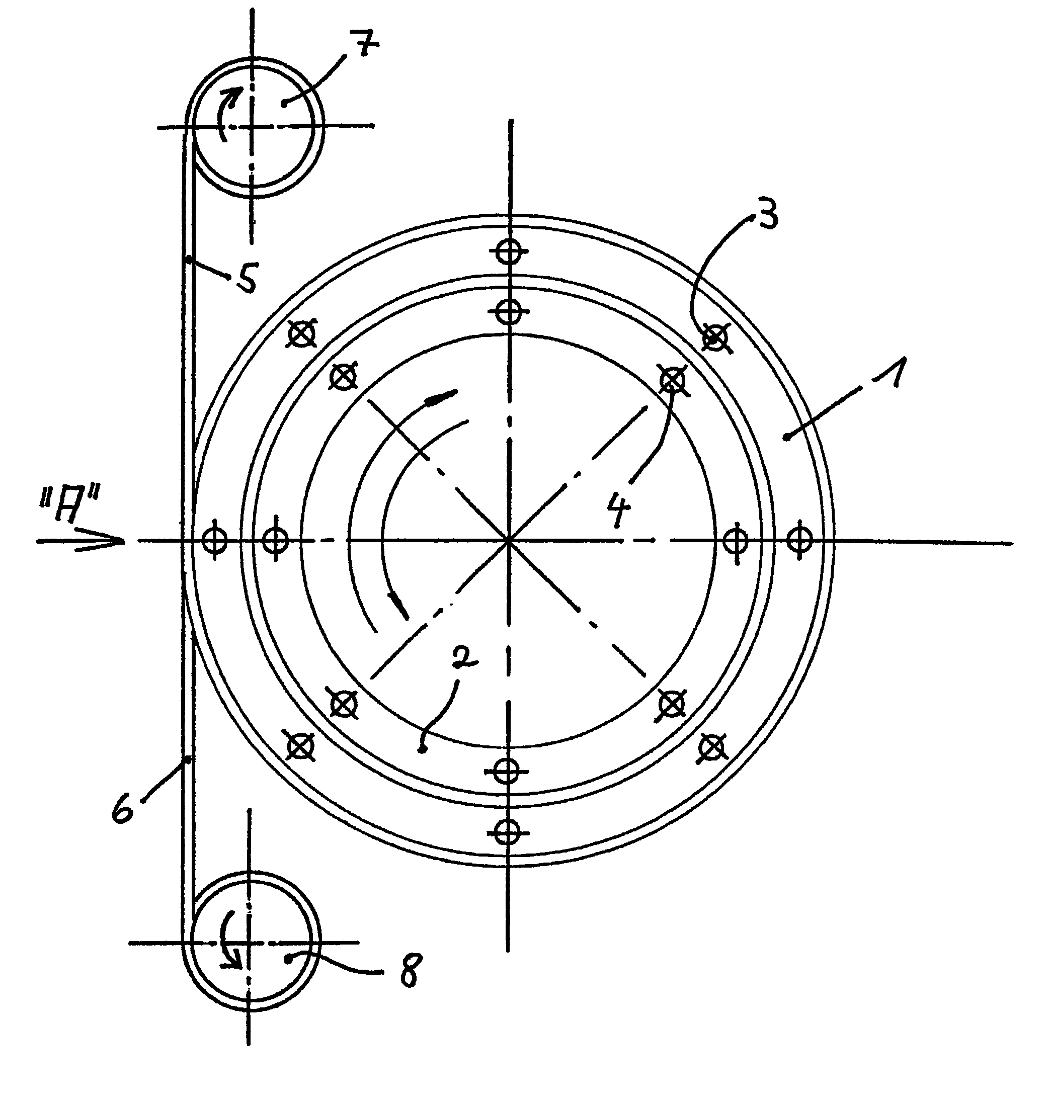
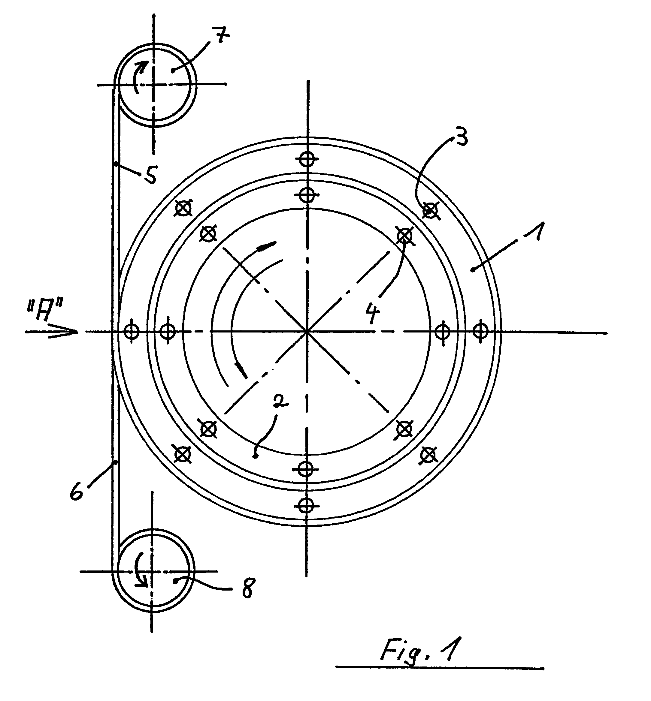
[0020]FIG. 1 illustrates a rotary joint mechanism comprised of a rotary joint that includes an outer ring 1 and an inner ring 2. The outer ring 1 is adapted to be connected to a rotatable machine or system part. For this purpose, the outer ring 1 is provided with connecting holes 3. The inner bearing ring 2 is also provided with connecting holes 4 so that the inner ring 2 can be connected to a fixed machine or system part.

[0021]FIG. 1 also shows that the rotary joint mechanism includes a cable element 5, 6 stretched between two drive spindles 7, 8 so that it encircles the outer ring 1 of the rotary joint one or more times (i.e. one or more complete revolutions). This construction provides a relatively simple way for driving the outer bearing ring 1 by way of the transmission of force through the cable element 5, 6.

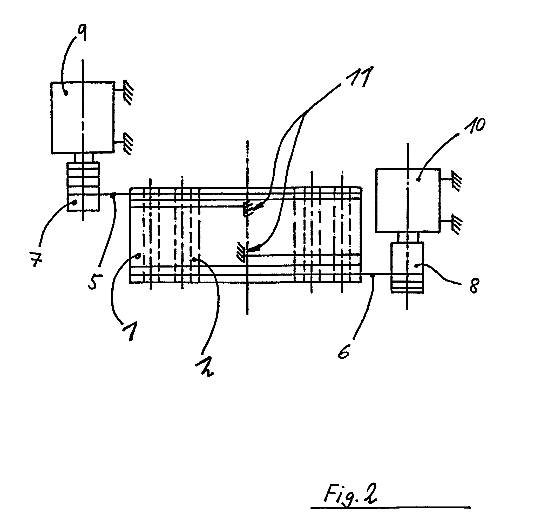
[0022]FIG. 2 is a side view of the rotary joint mechanism shown in FIG. 1 as seen from the direction indicated by the arrow A in FIG. 1. It can be seen that in the case of...


PUM


Abstract

A rotary joint mechanism for connecting two machine parts to effect relative movement between the two machine parts includes an outer ring adapted to be connected to a rotatable machine part, and an inner ring adapted to be connected to a fixed machine part, with the outer ring being rotatable relative to the inner ring. The outer surface of the outer ring is provided with a mechanism for transferring force from at least one cable element to the outer ring to effect rotation of the outer ring relative to the inner ring.

Description

FIELD OF THE INVENTION[0001]The present invention generally relates to a rotary joint. More particularly, the present invention pertains to rotary joints used in, for example, cranes, wind power plants and the like.BACKGROUND OF THE INVENTION[0002]Rotary joints are used in a variety of different applications including construction machinery, rotary cranes, and frequently also in wind power plants, although the uses are not limited in this regard. In such cases, it is generally necessary with the use of a generic rotary joint, in addition to effecting the rotatable connection of two machine or system parts, to also transfer for the active rotation of one of the two machine or system parts, a drive moment to this machine or system part, with the drive moment being usually provided by an electric or hydraulic drive.[0003]German Offenlegungsschrift No. DE 198 14 629 A1 discloses an arrangement for rotatably positioning the machine pod of a wind power plant. The torque is transferred fro...

Claims


Application Information

Patent Timeline
Patent Type & Authority Patents(United States)
IPC IPC(8): F16H19/00F16H55/36B66C23/84F03D80/00F03D80/70F16C11/04
CPCB66C23/84F03D11/00F16C11/04F05B2240/916Y10T74/18848Y02E10/722Y02E10/728Y10T74/1836F03D80/00F03D80/70Y02E10/72
Inventor LIESEGANG, HANS-JURGEN
Owner AB SKF
Why Eureka
Try Eureka