Check valve with locked restraint mechanism

a technology of locking mechanism and check valve, which is applied in the field of check valves, can solve the problems of adding time and expense to the provision of the valve, and the inability to easily scale down the movement of parts, so as to achieve reliable and controllable cracking pressure, prevent spring buckling, and easy and fast mounting

Active Publication Date: 2006-04-04
SMART PROD
View PDF3 Cites 5 Cited by
  • Summary
  • Abstract
  • Description
  • Claims
  • Application Information

AI Technical Summary

Benefits of technology

[0009]It is another advantage of the present invention to provide a check valve where the poppet and spring are self-aligning within the cavity of the housing.
[0010]It is a further advantage of the present invention to provide a check valve having a range of reliable and controllable cracking pressures.
[0011]It is a still further advantage of the present invention to provide a check valve which is well suited to automated assembly.
[0012]It is another advantage of embodiments of the present invention to provide a check valve which may easily and quickly mounted in a fixed position within a conduit without machining.
[0013]These and other advantages are provided by the present invention, which in embodiments relate to a check valve including a casing having a front end a back end and an interior cavity oriented generally along a longitudinal axis of the check valve. The casing includes a pair wings formed by slots at a back end of the casing, the wings capable of resiliently spreading apart from each other. The casing further includes a pair of ramps formed in wings on an interior surface of the casing, and a pair of holes formed through the wings and being adjacent to the at least one ramp. A seat section is further formed in the interior surface of the casing near the front end.
[0014]This embodiment of the check valve further includes a stopper capable of seating within the seat section, a spring for fitting within the interior cavity and having a first end capable of engaging the stopper and biasing the stopper into the seat section, and a restraining mechanism. The restraining mechanism includes a spherical base capable of engaging the second end of the spring, a centering shaft for extending along the longitudinal axis at least partially through a center of the spring and preventing buckling of the spring as it compresses, and a pair of locking ears extending generally radially outward from the longitudinal axis of the check valve. During assembly, the restraining mechanism is forced down into the internal cavity of the casing so that the locking ears ride down the ramps and into the holes to mount the restraining mechanism within the casing. In this position, the spring is compressed to maintain the stopper within the seat section.

Problems solved by technology

One problem in conventional check valves relates to mounting the valve within the flow conduit.
While it is known to machine a cavity into the conduit for seating the valve, such machining is adds time and expense to the provision of the valve.
Another problem with conventional check valves is that the moving parts are not easily scaled down for small inner diameter (“id”) conduits.

Method used


Image

  • Check valve with locked restraint mechanism
  • Check valve with locked restraint mechanism
  • Check valve with locked restraint mechanism

Examples


Embodiment Construction

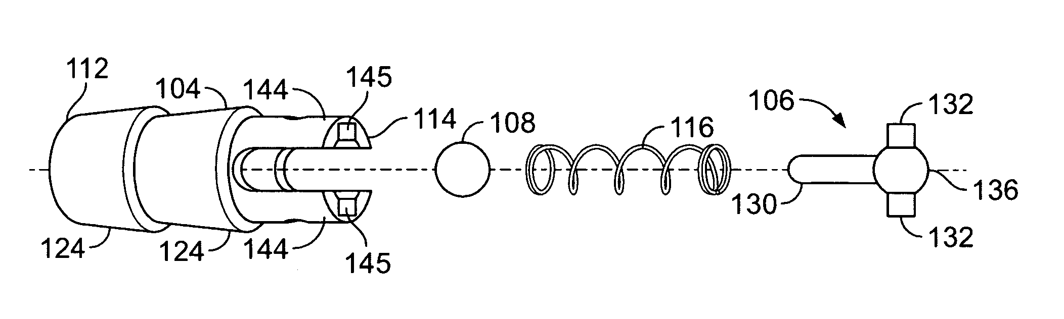
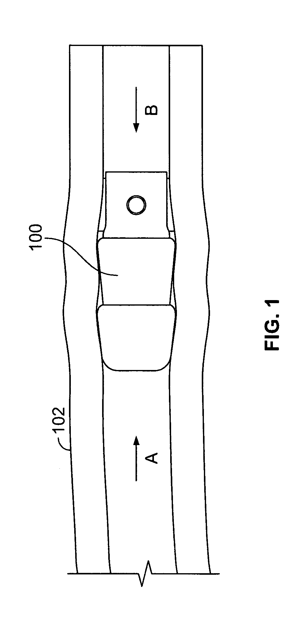
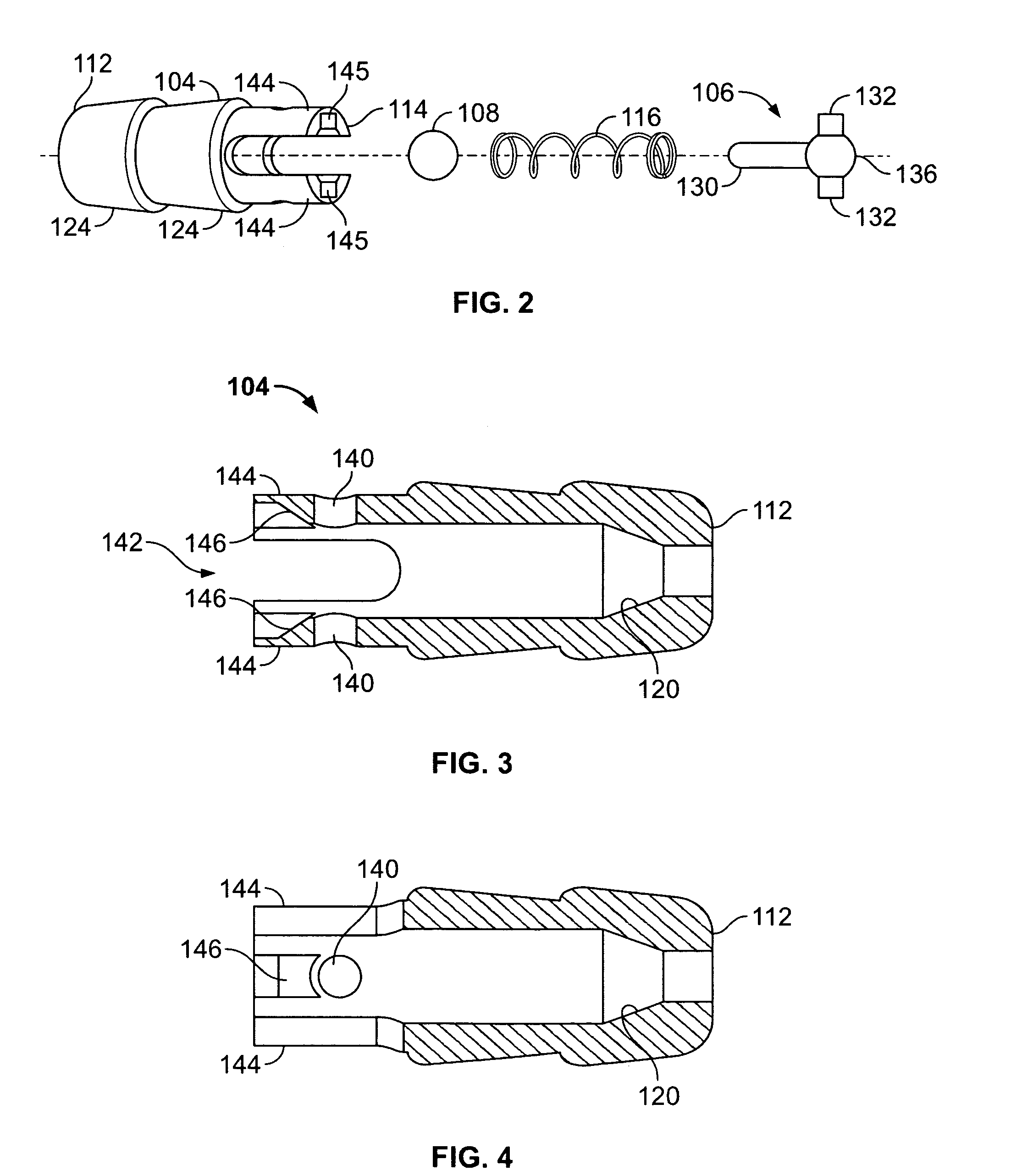
[0023]The present invention will now be described with reference to FIGS. 1 through 6, which embodiments relate to check valve which may be securely located within a conduit and which has a design capable of operating in narrow ID conduits. It is understood that the present invention may be embodied in many different forms and should not be construed as being limited to the embodiments set forth herein. Rather these embodiments are provided so that this disclosure will be thorough and complete and will fully convey the invention to those skilled in the art. Indeed, the invention is intended to cover alternatives, modifications and equivalents of these embodiments, which are included within the scope and spirit of the invention as defined by the appended claims. Furthermore, in the following detailed description of the present invention, numerous specific details are set forth in order to provide a thorough understanding of the present invention. However, it will be clear to those of...


PUM


Abstract

Check valves including components having a straightforward and simple design allowing the components to be scaled down to an extremely small size without losing functionality or performance of the check valve.

Description

BACKGROUND OF THE INVENTION[0001]1. Field of the Invention[0002]The present invention relates to check valves for one-way flow control and pressure relief within tubing, and in particular to check valves which may be anchored in place through the use of a barbed casing and check valves including components having a straightforward and simple design allowing the components to be scaled down to an extremely small size without losing functionality or performance of the check valve.[0003]2. Description of the Related Art[0004]Check valves are used in a wide variety of applications to provide accurate, reliable one-way fluid flow control and pressure relief. Applications in which check valves are typically used include medical diagnostic and treatment equipment, gas analysis equipment, filtration, beverage dispensing, semiconductor fabrication, chemical processing and many others.[0005]While many configurations are known, a typical check valve is comprised of an annular disc, or poppet, ...

Claims


Application Information

Patent Timeline
Patent Type & Authority Patents(United States)
IPC IPC(8): F16K15/02F16K15/04
CPCF16K15/044Y10T137/6086Y10T137/7504Y10T137/7927Y10T137/7929
Inventor JERNIGAN, JAY M.KLIEWER, CYRUSMCGREGOR, MICHAEL
Owner SMART PROD
Why Eureka
Try Eureka