Splicing for interconnected thin-walled metal structures

a thin-walled metal structure and interconnected technology, applied in the field of splicing, can solve the problems of relatively ineffective work hardening in the structure, achieve full effectiveness, reduce local effective maximum tension load, and improve flight characteristics of the aircraft

Inactive Publication Date: 2006-04-04
AIRBUS OPERATIONS GMBH
View PDF4 Cites 15 Cited by
  • Summary
  • Abstract
  • Description
  • Claims
  • Application Information

AI Technical Summary

Benefits of technology

[0013]Another advantage of the invention is seen in that additional methods can be employed for a targeted reduction of the locally effective maximum tension load. One such method involves work hardening. More specifically, a rivet hole is plastically deformed in the radial direction by widening the rivet hole for generating in the wall of the rivet hole tangentially effective residual compression stress which counteracts the effective tension load on the rivet hole. It is known from experiment that this work hardening is relatively ineffective in a structure subject to a large secondary bending load. However, it has been found that the work hardening of the rivet holes in combination with the invention can develop its full effectiveness in the conventional rivet row or rows because the additional rivet row according to the invention has deflected secondary bending loads from the conventional rivet rows by taking up such secondary bending loads itself. More specifically, secondary bending loads are now primarily effective only in the additional rivet row which neutralizes such bending loads by the limited relative movement between the sheet metal end portions.
[0014]A still further advantage of the invention is seen in that the flight characteristics of an aircraft have been improved by the teaching of the invention.

Problems solved by technology

It is known from experiment that this work hardening is relatively ineffective in a structure subject to a large secondary bending load.

Method used


Image

  • Splicing for interconnected thin-walled metal structures
  • Splicing for interconnected thin-walled metal structures
  • Splicing for interconnected thin-walled metal structures

Examples


Embodiment Construction

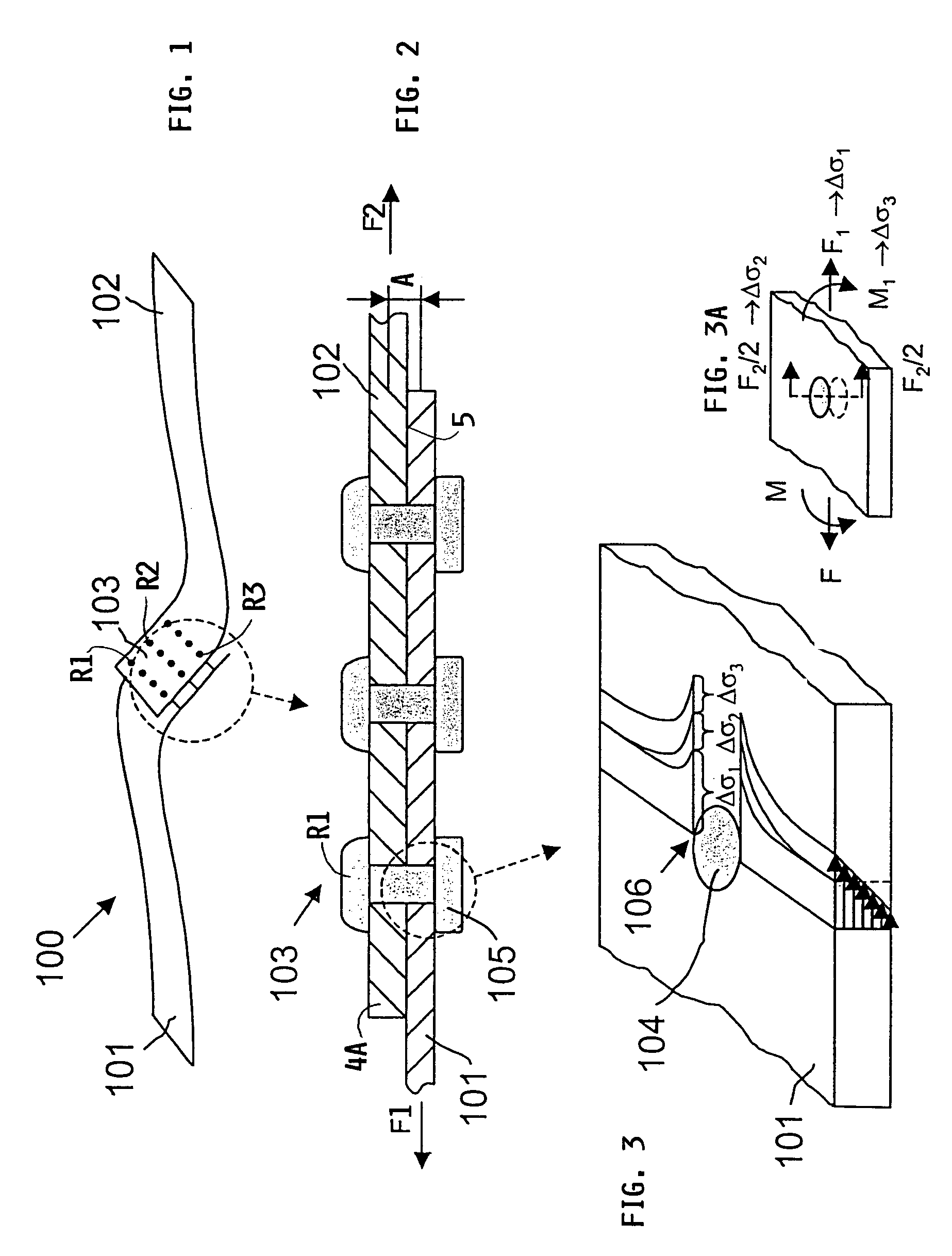
[0024]FIGS. 1 to 3 illustrate a conventional rivet splice connection between skin sections 101 and 102 of an aircraft structure 100. Three rows R1, R2 and R3 of rivets form the splice 103. During operation of an aircraft the so constructed aircraft structure 100 is exposed to a cyclical or dynamic tensional load, which causes locally a bending load which flexes the splice as shown within the dashed circle in an exaggerated manner in connection with sheet metal materials that are conventionally used for the construction, for example of an aircraft body skin. There is the potential danger of material fatigue, particularly in the splice accompanied by crack formations following by crack spreading or crack progression. Individual cracks, and particularly the interaction of a plurality of cracks causing a widespread fatigue damage may substantially reduce the strength characteristics of the aircraft structure.

[0025]Referring to FIG. 2, the bending load effective in the splice is referred...


PUM

PropertyMeasurementUnit
areaaaaaaaaaaa
stressaaaaaaaaaa
interlocking forceaaaaaaaaaa

Abstract

A rivet splice that holds an upper and a lower sheet metal end portion together includes at least one row (6) of rivets that is subject to dynamic loads and a further row (7) of rivets that holds the sheet metal end portions together so that a limited sliding motion between the sheet metal end portions is possible. The further row (7) of rivets is positioned between an end edge (4A) of an upper sheet metal end portion and the at least one row (6) of rivets. The limited sliding motion provides a load relief of the at least one row of rivets thereby reducing the starting of cracks at the walls of the rivet holes and impeding the spreading of cracks.

Description

PRIORITY CLAIM[0001]This application is based on and claims the priority under 35 U.S.C. § 119 of German Patent Application 102 38 820.2, filed on Aug. 23, 2002, the entire disclosure of which is incorporated herein by reference.FIELD OF THE INVENTION[0002]The invention relates to a device, also referred to as splicing, for connecting thin-walled sheet metal end portions to each other in an overlapping contact surface area. At least one row of rivets subject to cyclical or dynamic loads is arranged in the overlapping area for splicing the two sheet metal end portions to one another.BACKGROUND INFORMATION[0003]At the present time rivet connections described above are the predominantly used splicing connections in aircraft construction.[0004]In such conventional splicing connections an interlocking is achieved between the parts to be interconnected by a mechanical interlocking of geometric shapes to thereby provide an interlocking splice connection. In such connections it is necessary...

Claims


Application Information

Patent Timeline
Patent Type & Authority Patents(United States)
IPC IPC(8): F16B5/04B21J15/02
CPCB21J15/02B21J15/142Y10T29/49956Y10T29/49948Y10T403/75Y10T29/49943
Inventor ASSLER, HERWIGSCHMIDT, HANS-JUERGEN
Owner AIRBUS OPERATIONS GMBH
Why Eureka
Try Eureka