Scroll fluid machine

a fluid machine and roller technology, applied in the direction of machines/engines, rotary/oscillating piston pump components, liquid fuel engines, etc., can solve the problems of reducing energy efficiency, conventional techniques do not take into account the entrainment of lubricating oil into the working fluid, etc., to achieve the effect of reducing the loss of oil heating and high energy efficiency

Active Publication Date: 2006-04-04
HITACHI JOHNSON CONTROLS AIR CONDITIONING INC
View PDF10 Cites 13 Cited by
  • Summary
  • Abstract
  • Description
  • Claims
  • Application Information

AI Technical Summary

Benefits of technology

[0008]It is a further object of the invention to eliminate direct mixing of oil, which lubricates a shaft support of an orbiting scroll member and a shaft support for a crankshaft, with a working fluid having passed through a suction port, prevent heating of the working fluid

Problems solved by technology

The conventional techniques take no sufficient account of entrainment of lubricating oil into a working fluid, which is sucked and compressed.
In particular, with the arrangement, in which the balance weight is arranged in the backpressure chamber to provide for a cantilever bearing construction, oil for lubrication of a shaft support of an orbiting scroll member and a shaft support for a

Method used


Image

  • Scroll fluid machine
  • Scroll fluid machine
  • Scroll fluid machine

Examples


first embodiment

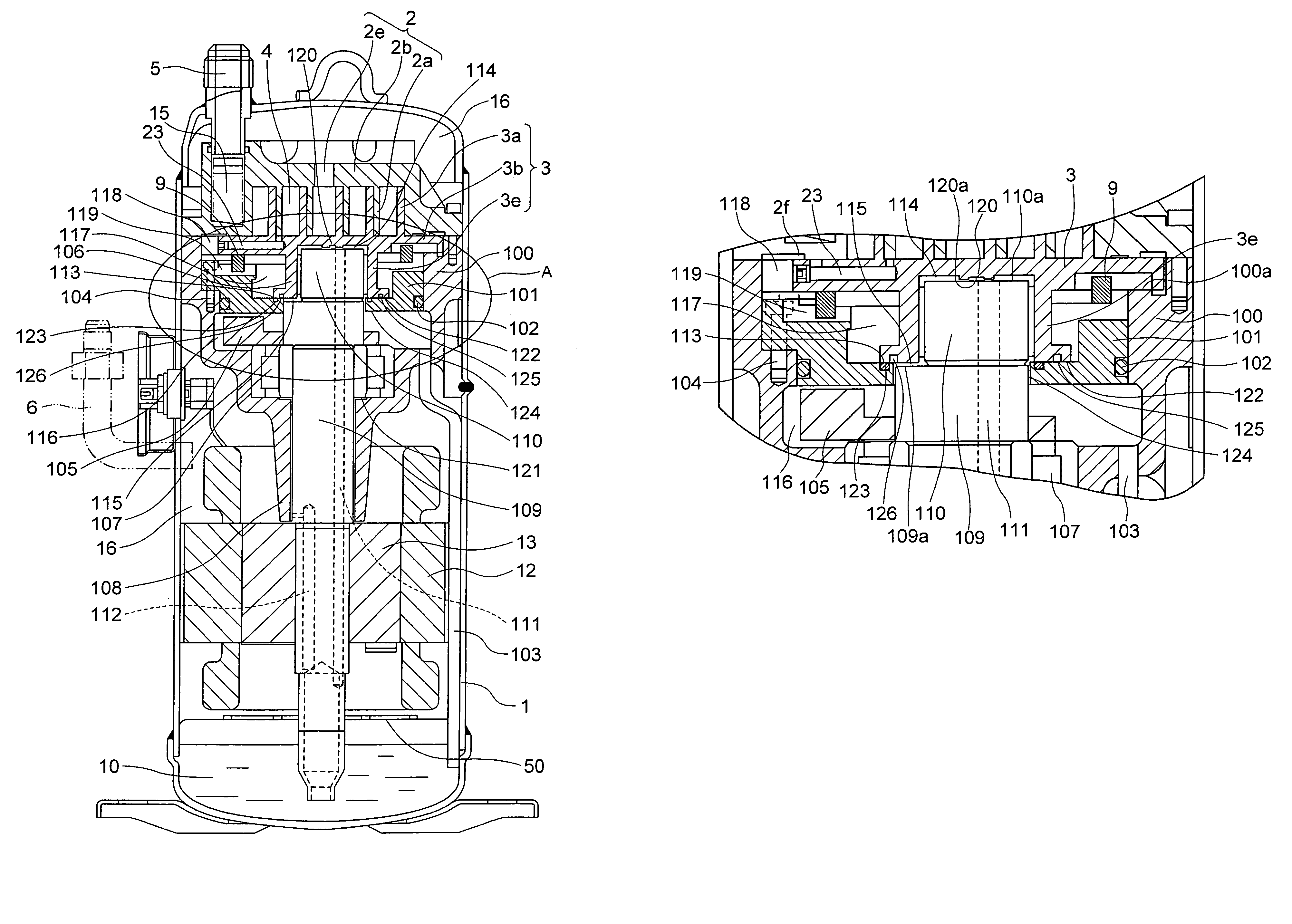
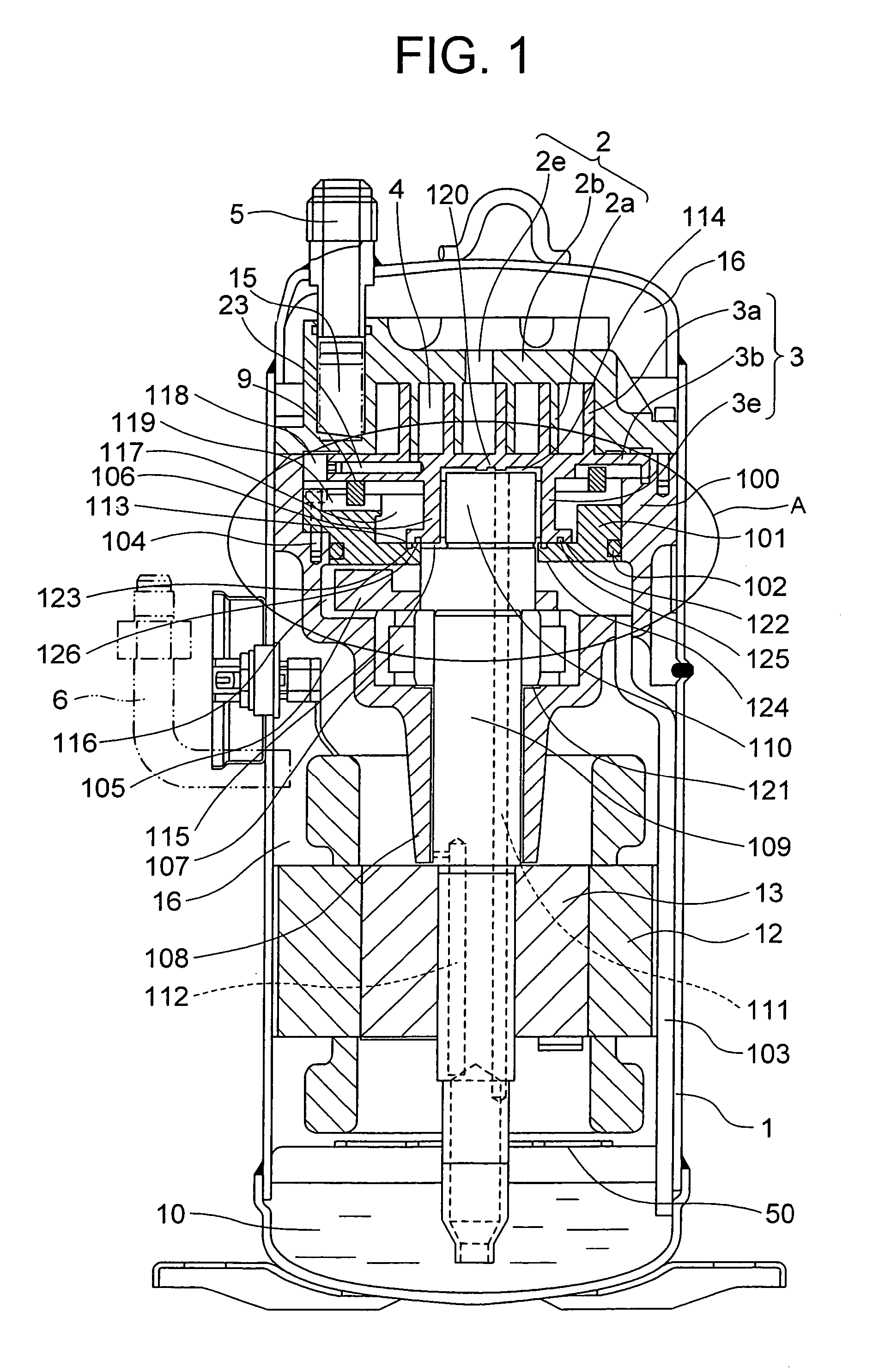
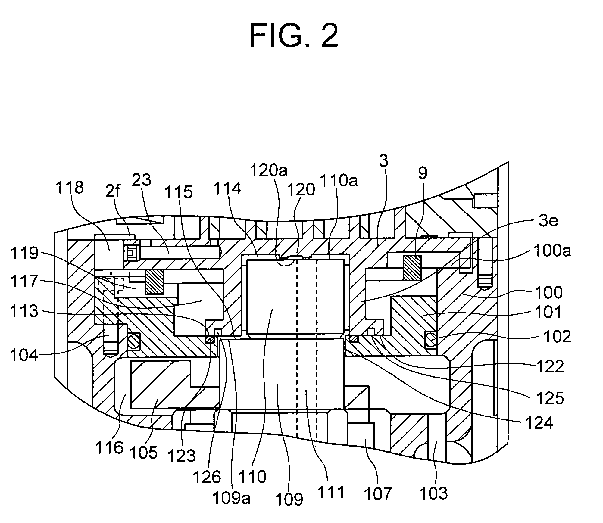
[0030]the invention will be described with reference to FIGS. 1 and 2.

[0031]First, a whole construction of a scroll fluid machine according to the embodiment will be described with reference to FIG. 1.

[0032]Fundamental components of a compression section comprise a stationary scroll 2, an orbiting scroll 3, and a first frame 100, and the first frame 100 is fixed to a closed vessel 1. The stationary scroll 2 essentially comprises a wrap 2a, an end plate 2b, and a discharge port 2e, and the orbiting scroll 3 essentially comprises a wrap 3a, an end plate 3b, and a shaft support 3e. Compression chambers defined when the stationary scroll 2 and the orbiting scroll 3 mesh with each other are decreased in volume upon orbiting movement of the orbiting scroll 3 to perform compressive actions. Accompanying with the orbiting movement of the orbiting scroll 3, a working fluid is sucked into the compression chambers 4 via a suction port 5 and a suction space 15 and discharged from a discharge po...


PUM


Abstract

A second frame is arranged between a first frame and an orbiting scroll, and a central space and an outer peripheral space are sealed off by a seal portion, which is formed between an end surface of a shaft support of the orbiting scroll and the second frame. Also, a balance weight is arranged in a space between an underside of the second frame and the first frame. Thereby, most of an oil having lubricated respective shaft supports flows into the space below the second frame, and the oil accumulated in the space is discharged through an oil scavenge pipe into an oil reservoir in a lower portion of a closed vessel. Also, since the balance weight can be assembled from a side of the orbiting scroll in a state, in which the second frame is removed, it is possible to mount the balance weight close to the orbiting scroll.

Description

BACKGROUND OF THE INVENTION[0001]The present invention relates to a scroll fluid machine, in which a refrigerant, air, or other compressible gases work, and specifically is preferable to be applied to scroll compressors of a cantilever bearing support construction used in refrigerating / air-conditioning equipment.[0002]Scroll compressors are widely used, as compressors for refrigerating / air-conditioning equipment, in various fields, and are superior in efficiency, reliability and calmness to compressors of other systems.[0003]As a conventional scroll fluid machines, there is one disclosed in, for example, JP-A-8-121366. A seal member is provided between an orbiting scroll member and a frame, and a backpressure chamber is formed on an opposed side of the orbiting scroll member to a wrap. The backpressure chamber comprises, on account of the seal member, a first space disposed centrally to be under pressure substantially equal to a discharge pressure, and a second space disposed on an ...

Claims


Application Information

Patent Timeline
IPC IPC(8): F03C2/00F04C2/00F04C27/00F04C18/02F04C23/00F04C29/00F04C29/02
CPCF04C29/0021F04C29/023F04C23/008F04C2240/807F04C29/026F04C2230/605F04C18/0215
Inventor TSUCHIYA, TAKESHIMIZUNO, TAKAOMATSUNAGA, MUTSUNORIOHTAHARA, MASARUYASUNORI, SYUNSUKEHAYASE, ISAOTSUBONO, ISAMUFUJIMURA, KAZUYUKI
Owner HITACHI JOHNSON CONTROLS AIR CONDITIONING INC
Why Eureka
Try Eureka