Golf club head and manufacturing method therefor

a manufacturing method and golf club technology, applied in the field of golf club heads, can solve the problems of weakening the entire structural strength reducing the product quality, and unable to effectively adjust the center of gravity and the total weight of the main body, so as to reduce the wrinkles

Inactive Publication Date: 2006-04-04
FUSHENG PRECISION
View PDF19 Cites 18 Cited by
  • Summary
  • Abstract
  • Description
  • Claims
  • Application Information

AI Technical Summary

Benefits of technology

[0008]The primary objective of this invention is to provide a golf club head and a manufacturing method therefor, wherein a cushion channel is remained between the through holes on the main body of the golf club head and the carbon-fiber plates to form an appropriate clearance for absorbing deformation to reduce the wrinkles and the influence thereof on the entire structural strength.

Problems solved by technology

Since the main body is made of metal, the center of gravity and the total weight of the main body cannot be effectively adjusted specific.
In manufacture operation, it reduces the product quality due to irregular deformation of the prepared carbon-fiber fabrics.
Moreover, a large area of the prepared carbon-fiber fabrics may weaken the entire structural strength of the main body and it may lower its striking sound instead of a sharp striking sound making by a metal golf club head.

Method used


Image

  • Golf club head and manufacturing method therefor
  • Golf club head and manufacturing method therefor
  • Golf club head and manufacturing method therefor

Examples


first embodiment

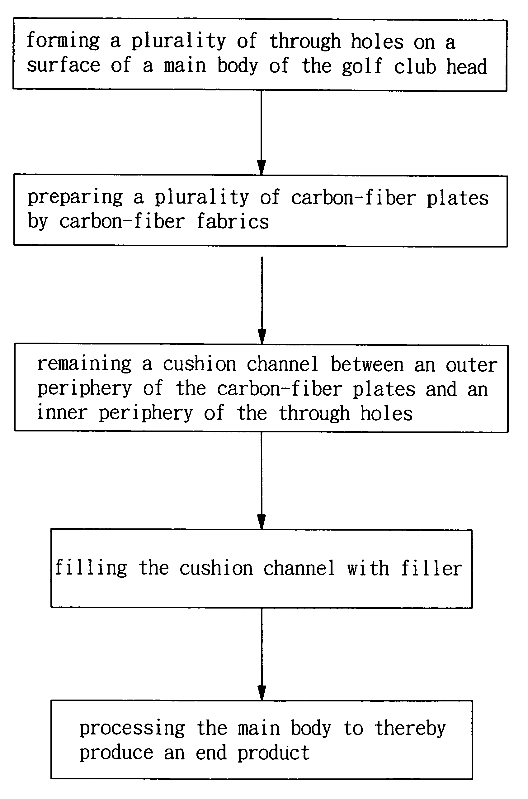
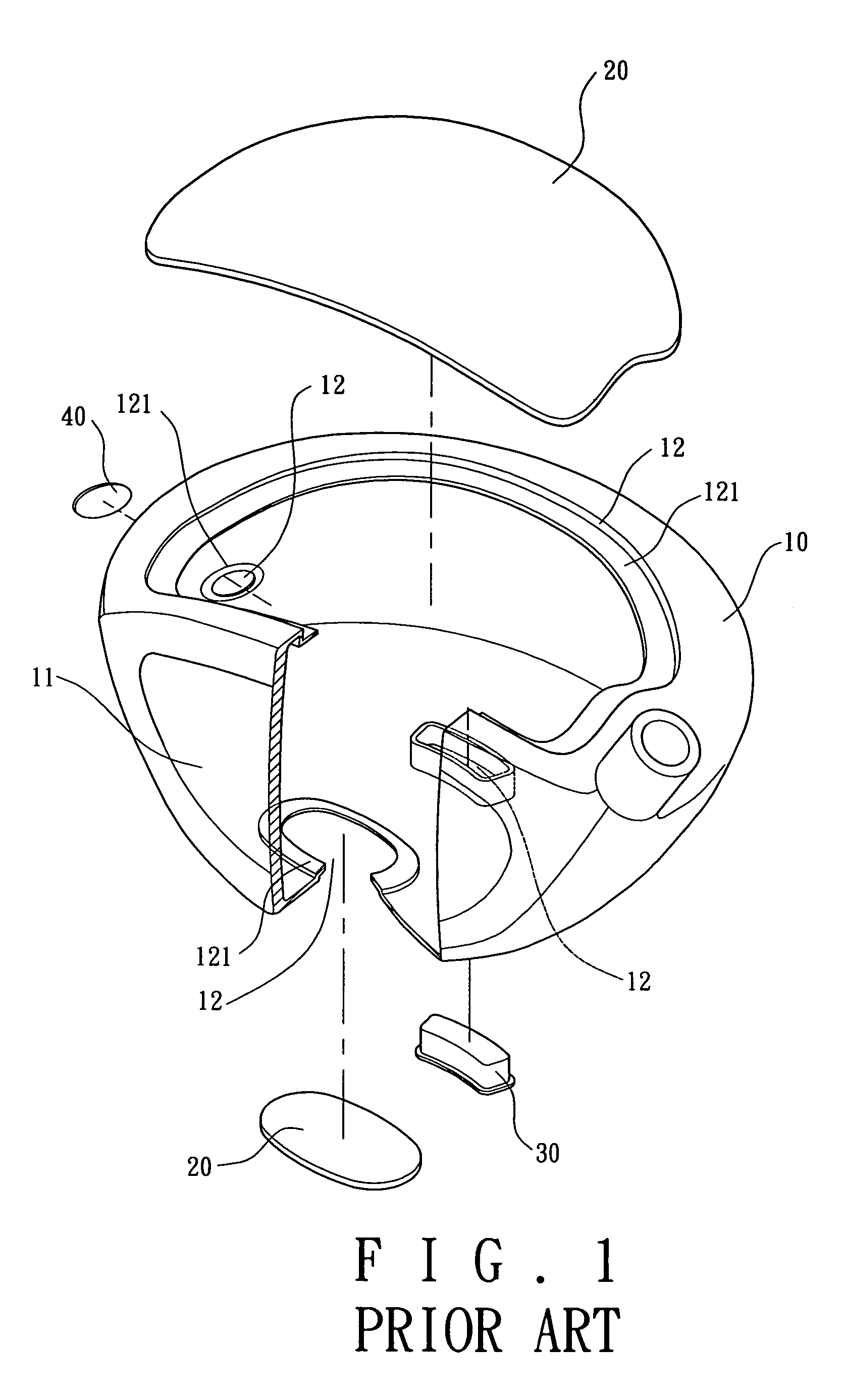
[0026]Referring to FIGS. 3 and 4, the first step of the manufacture method in accordance with the present invention is forming a plurality of through holes 12 on the surface of the main body 10 of the golf club head. The main body 10 is preferably formed as a single member by casting and the material thereof can be stainless steel, titanium alloy, or iron etc. A striking plate 11 is attached to the front of the main body 10 by welding, integrally forming or embedding. An appropriate amount of the through holes 12 are formed on the crown plate, the sole plate or the side plate of the main body 10. A stepped portion 121 is formed on the peripheral of the through holes 12 for supporting a carbon-fiber plate 20, a weighting member 30 and a name plate 40 (as shown in FIG. 1) of predetermined size in the following procedure.

[0027]Referring to FIGS. 3 and 4, the second step of the manufacture method in accordance with the first embodiment in the present invention is preparing a plurality o...

second embodiment

[0034]Furthermore, as shown in FIGS. 11 through 13, when the size of the through holes 12 and the carbon-fiber plate 20 is too large to form cushion channel a, it a is disadvantage of a CNC milling process to mill the periphery of the through holes 12 and the carbon plate 20. Alternatively, a first stepped portion 122 and a second stepped portion 123 of the second embodiment in the present invention can be used to position the large carbon-fiber plate 20 on the large through holes 12 so as to form the cushion channel with a uniform width or various widths.

[0035]Referring to FIGS. 3, 4 and 8 through 10, the third embodiment of the present invention is disclosed. Compared with the first and second embodiments, the third step of the manufacture method in the third embodiment is provided with plural short fingers 21 on the outer periphery of the carbon-fiber plate 20 to maintain the cushion channel a. The size of the outer periphery of the carbon-fiber plate 20 in the embodiment is slig...

third embodiment

[0036]As shown in FIGS. 11 through 13, the short fingers 21 of the carbon-fiber plate 20 in the third embodiment can also be adapted to support a large carbon-fiber plate 20 on a large through hole 12 for forming cushion channel a with a uniform width or various widths.

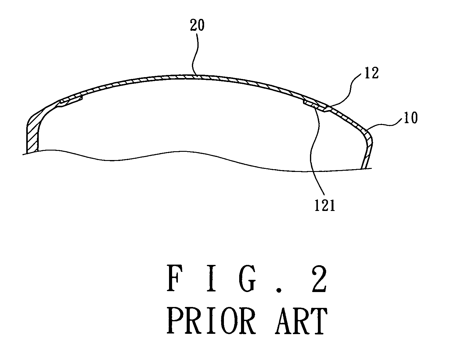
[0037]As described above, the conventional carbon-fiber plate 20 is closely fitted with the through hole 12 on the main body 10, thereby plastic deformation and wrinkles occur constantly. However, the golf club head and the manufacture method therefor in the present invention indeed maintain the structural strength of the main body 10 and promote the quality and the product price.


PUM

PropertyMeasurementUnit
sizeaaaaaaaaaa
elasticaaaaaaaaaa
gravityaaaaaaaaaa

Abstract

A golf club head and manufacturing method. The method includes the steps of: selectively forming through holes on a surface of a golf club head; preparing carbon-fiber plates which are made of prepared carbon-fiber fabrics; providing a cushion channel between an outer periphery of the carbon-fiber plate and an inner periphery of the through hole while each of the carbon-fiber plate is combined with the associated through hole of the golf club head; filling the cushion channel with a filler; and finishing the golf club head to produce an end product.

Description

BACKGROUND OF THE INVENTION[0001]1. Field of the Invention[0002]The present invention is related to a golf club head and a manufacturing method therefor. More particularly, the present invention is related to a cushion channel remained between through holes of the main body of the golf club head and prepared carbon fiber plates as well as related to a elastic colored filler filled in the cushion channel to prevent wrinkle on the periphery of the through holes and the carbon fiber plates.[0003]2. Description of the Related Art[0004]A conventional golf club head mainly includes a main body and a striking plate attached thereto, all of which are made of metal or alloy. The main body is formed as a single member by casting or consisted of a crown plate, a sole plate and a side plate by welding. As to the striking plate, it is attached to a front surface of the main body by incorporating, welding or embedding. To meet various requirements, manufacture may change the configuration and the...

Claims


Application Information

Patent Timeline
Patent Type & Authority Patents(United States)
IPC IPC(8): A63B53/04A63B102/32
CPCA63B53/0466A63B2053/0437A63B2053/0433A63B2209/023A63B53/0437A63B53/0433
Inventor CHEN, YUN-FANG
Owner FUSHENG PRECISION
Why Eureka
Try Eureka