Biosensor with interdigitated electrodes

a biosensor and electrode technology, applied in the field of biosensors, can solve the problems of poor accuracy, affecting a large extent, and all poorly specific to sugars

Inactive Publication Date: 2006-04-04
PHC HLDG CORP
View PDF14 Cites 132 Cited by
  • Summary
  • Abstract
  • Description
  • Claims
  • Application Information

AI Technical Summary

Problems solved by technology

These methods, however, are all poorly specific to sugars and hence have poor accuracy.
Among these methods, the polarimetry is simple in manipulation, but is largely affected by the temperature during the manipulation.
Therefore, the polarimetry is not suitable as a method of simple quantification of sugars at home, etc. for ordinary people.
However, as speculated from the reaction process, it has a drawback in that the measurement is largely affected by the oxygen concentration of the sample, and if the oxygen is absent in the sample, the measurement is infeasible.
When a sample in an extremely small amount is measured by a conventional electrochemical glucose sensor, the amount of glucose in the sample is also extremely small, and hence the sensitivity of the measurement may lower in some cases.

Method used


Image

  • Biosensor with interdigitated electrodes
  • Biosensor with interdigitated electrodes
  • Biosensor with interdigitated electrodes

Examples


embodiment 1

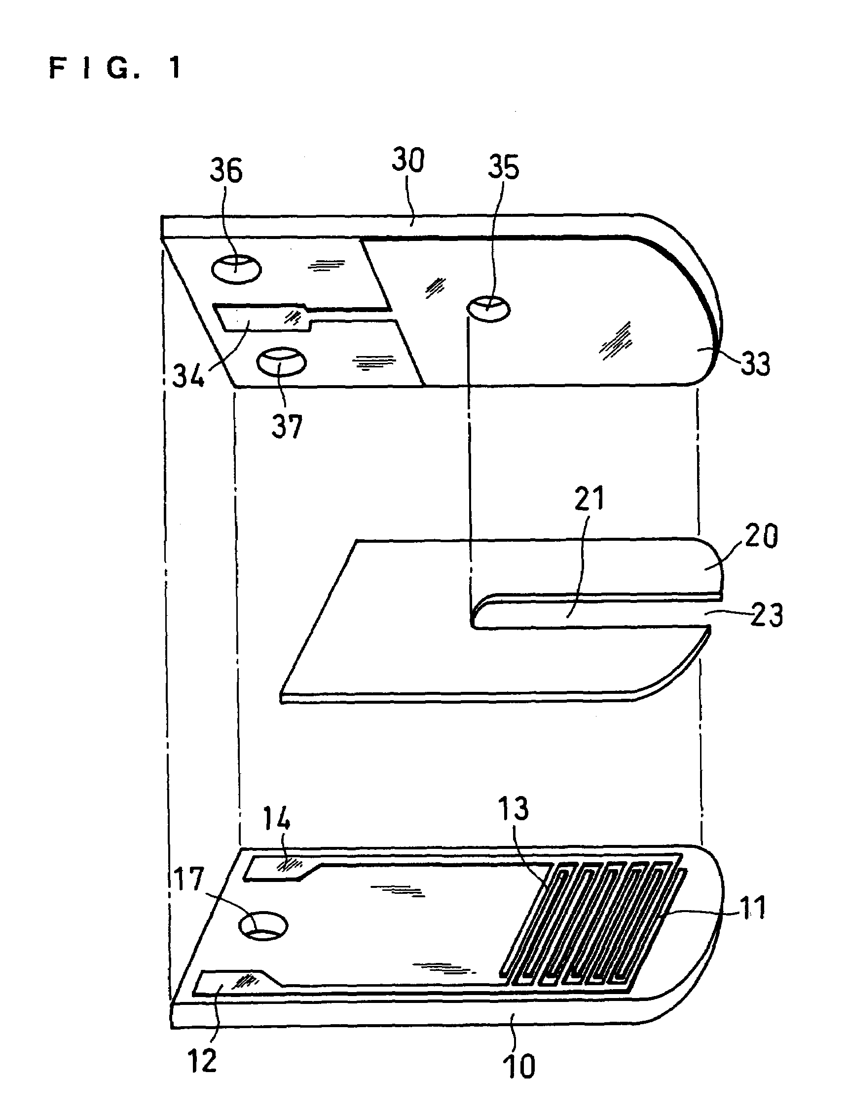
[0029]FIG. 1 is a longitudinal cross-sectional view of a glucose sensor from which the reagent layer and surfactant layer are omitted in this embodiment.

[0030]10 represents a first base plate comprising an electrically insulating material. On the base plate 10, there is formed, by photo lithography, an electrode system which is composed of a substantially comb-shaped working electrode 11 comprising a plurality of branches and its lead 12 and a substantially comb-shaped first counter electrode 13 comprising a plurality of branches and its lead 14. As a specific method, for example, palladium is sputtered over the base plate, and the palladium film is covered with a resist. Subsequently, the resultant palladium film is provided with masking having the same shape as the electrode system, exposed to light, developed, and etched. Finally, the resist is removed to form an electrode system having a predetermined shape. In this figure, each of the working electrode 11 and the first counter ...

embodiment 2

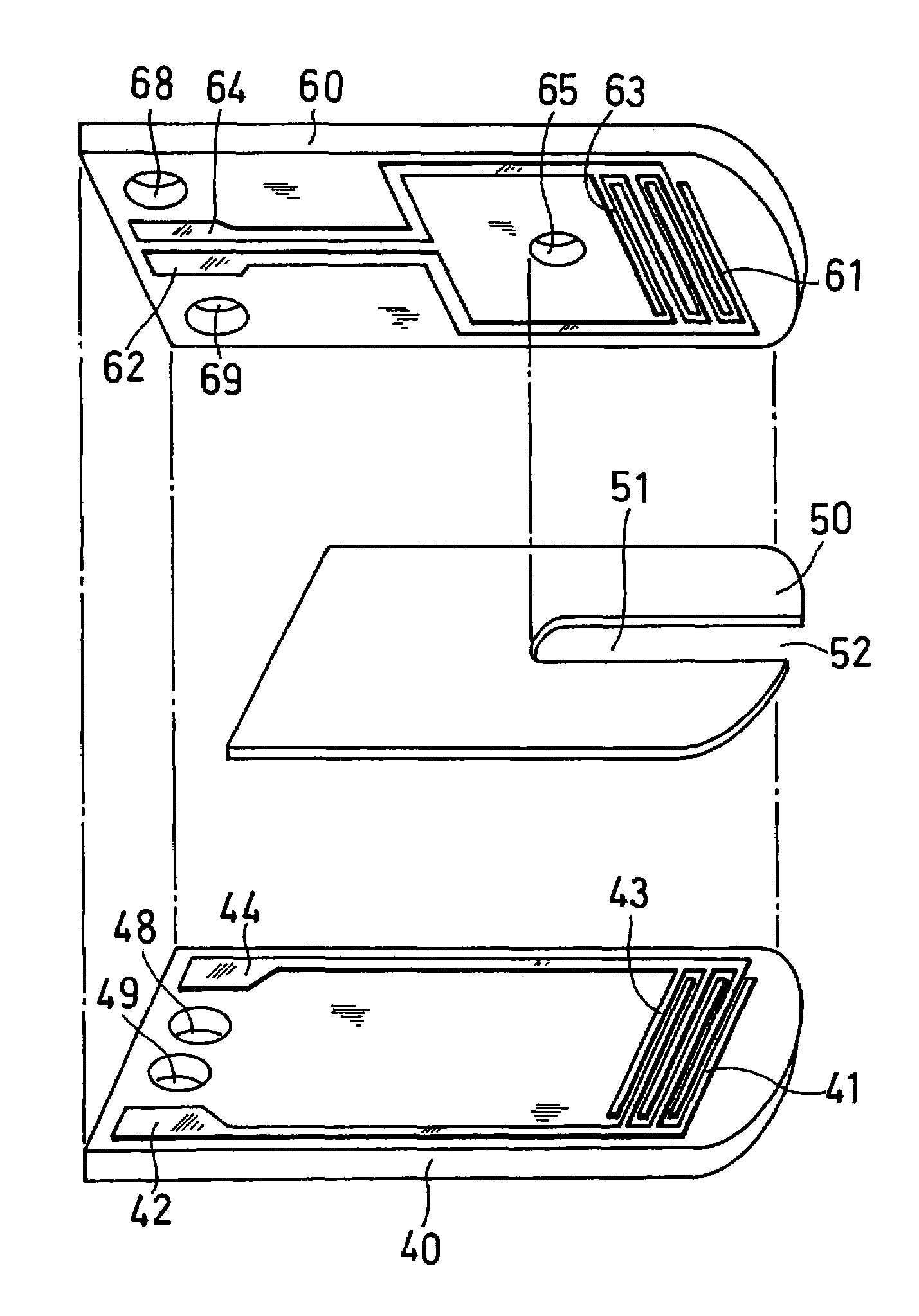
[0039]FIG. 4 is a decomposed perspective view of a glucose sensor from which the reagent layer and surfactant layer are omitted in this embodiment.

[0040]Following the same procedure as that of Embodiment 1, a first electrode system, which is composed of a substantially comb-shaped first working electrode 41 comprising a plurality of branches, a first working electrode lead 42, a substantially comb-shaped first counter electrode 43 comprising a plurality of branches and a first counter electrode lead 44, is formed on a first base plate 40. On a second base plate 60 is formed a second electrode system, which is composed of a substantially comb-shaped second working electrode 61 comprising a plurality of branches, a second working electrode lead 62, a substantially comb-shaped second counter electrode 63 comprising a plurality of branches and a second counter electrode lead 64. The number of the branches of the working electrode and the counter electrode is not to be limited to the num...

embodiment 3

[0045]FIG. 6 is a decomposed perspective view of a glucose sensor from which the reagent layer and surfactant layer are omitted in this embodiment.

[0046]The structure is the same as that of Embodiment 1 except for the formation of a reference electrode 15 and its lead 16 on a first base plate 10 and formation of an electrically connecting hole 38 for bringing a working electrode lead 12 and the lead 16 of the reference electrode 15 in contact with two corresponding terminals of an apparatus on a second base plate 30.

[0047]In the following, a measuring apparatus for measuring glucose with the use of this sensor will be described with reference to FIG. 9.

[0048]A sensor 80, which was described above, is shown on the left side of FIG. 9. In this figure, only the working electrode lead 12, the lead 16 of the first reference electrode, a counter electrode lead 14 and a lead 34 of a second counter electrode are shown. Meanwhile, a measuring apparatus 81 comprises connectors 72, 96, 74 and ...


PUM

PropertyMeasurementUnit
voltageaaaaaaaaaa
widthaaaaaaaaaa
widthaaaaaaaaaa

Abstract

The present invention provides a highly sensitive biosensor capable of yielding good response even when the amount of a sample is extremely small. The biosensor of the present invention includes: a first insulating base plate which has a working electrode comprising a plurality of branches and a first counter electrode comprising a plurality of branches, the branches of the working electrode and the first counter electrode being arranged alternately; a second insulating base plate which has a second counter electrode and which is disposed at a position opposite to the first insulating base plate; a reagent system comprising an oxidoreductase; and a sample supply pathway formed between the first and second insulating base plates, wherein the branches of the working electrode and the first counter electrode that are arranged alternately, the second counter electrode, and the reagent system are exposed in the sample supply pathway.

Description

CROSS-REFERENCE TO RELATED APPLICATION[0001]This application is the national phase under 35 U.S.C. §371 of PCT International Application No. PCT / JP02 / 05129, which has an international filing date of May 27, 2002, and which designated the United States of America.TECHNICAL FIELD[0002]The present invention relates to a biosensor for rapid and highly accurate quantification of a substrate contained in a sample.BACKGROUND ART[0003]Methods using polarimetry, colorimetry, reductimetry and a variety of chromatographies have been developed as methods for quantitative analysis of sugars such as sucrose and glucose. These methods, however, are all poorly specific to sugars and hence have poor accuracy. Among these methods, the polarimetry is simple in manipulation, but is largely affected by the temperature during the manipulation. Therefore, the polarimetry is not suitable as a method of simple quantification of sugars at home, etc. for ordinary people.[0004]Recently, various types of biosen...

Claims


Application Information

Patent Timeline
Patent Type & Authority Patents(United States)
IPC IPC(8): G01N27/327G01N27/26C12Q1/00C12Q1/26
CPCC12Q1/001C12Q1/26C12Q1/006G01N27/3272
Inventor TANIIKE, YUKOIKEDA, SHINYOSHIOKA, TOSHIHIKO
Owner PHC HLDG CORP
Why Eureka
Try Eureka