Controller circuit

a controller circuit and controller technology, applied in the field of lighting, can solve the problems of inability to control the inability to achieve the pwm control of leds always technically appropriate, and the inability to control leds in time, so as to reduce the complexity of the controller, maximize the lifetime of the led, and ensure the effect of constant current sour

Inactive Publication Date: 2006-04-04
PENTAIR POOL PROD INC
View PDF10 Cites 83 Cited by
  • Summary
  • Abstract
  • Description
  • Claims
  • Application Information

AI Technical Summary

Benefits of technology

[0011]According to one aspect of the invention, herein described, is a controller circuit for an array of light emitting diodes (LEDs) that uses a single constant current source, a multiplexer, and a short circuit to control the current supplied to a number of LEDs in a lighting array. An algorithm executed, for example, by a microcontroller rapidly switches the output of the current source between the various LEDs and a short circuit by varying the average time that each of the LEDs is connected to the current source so the average current for that LED can be set. The current source output is switched to the short circuit during the intervals when none of the LEDs are connected, thereby allowing a simple, constant current source to be used. In order to maximize the lifetime of the LEDs, an output filter may be incorporated into each LED drive channel so as to smooth out the current waveform applied to the LEDs.
[0012]In one embodiment of the invention, the current source is a switched mode converter circuit and the multiplexer is incorporated into the switch-mode circuit. This configuration offers the additional advantages of reducing the complexity of the controller and improving its power efficiency. When the switching frequency of the multiplexer is arranged to be synchronous with the switching frequency of the current source, additional improvements in efficiency are made by switching the multiplexer during the charging phase of the converter. When combined with a switch-mode current source, the number of components required for the output filters may be reduced as some may be shared between the various output channels.

Problems solved by technology

Thus, illumination from the LED systems is susceptible to being controlled by a computer program to provide complex, pre-designed patterns of light in virtually any environment.
However, PWM control of LEDs is not always technically appropriate and alternative approaches to conventional PWM control may capable of providing at least one of lower manufacturing cost, more efficient power conversation when energizing LEDs, or greater physical compactness.
In the former case, the LEDs are driven with a discontinuous waveform, thereby comprising their lifetime for a given brightness; in the latter, each variable current source entails significant extra cost.

Method used


Image

  • Controller circuit
  • Controller circuit
  • Controller circuit

Examples


Embodiment Construction

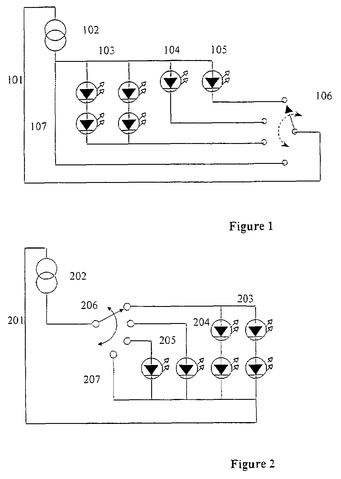
[0020]FIG. 1 shows a general lighting circuit 101 embodying the present invention. The circuit 101 includes a constant current source 102 for supplying independent circuit branches 103, 104, 105 equipped respectively with light emitting diodes (LEDs) and a short circuit conductor 107. A multiplexer 106 provides means for independently selecting one of more of the diode branches 103, 104, 105 and the short circuit 107.

[0021]FIG. 2 shows another example of a general lighting circuit 201. The circuit 201 includes a constant current source 202, various branches equipped with LEDs 203, 204, 205, a short circuit 207, and a multiplexer 206. Notwithstanding the different circuit layout of FIG. 2, these lighting circuits 101, 102 may be regarded as functionally equivalent.

[0022]In use, the multiplexer 106, 206 is driven by a control circuit capable of switching among the diode and short-circuit connections. The control circuit switching modes are designed to vary the average time that each o...


PUM


Abstract

A circuit used to control the brightness of a number of light emitting diodes (LEDs) in an array, such that the color and brightness of the light produced by the array may be varied. The circuit is optimized to operate at high efficiency, permitting its use in confined spaces with poor cooling. The circuit permits a variety of configurations of LEDs to be controlled and driven from a range of line voltages. The circuit is further optimized to use few components to achieve its function.

Description

[0001]This application claims priority of United Kingdom Application No. 0321008.5, filed on Sep. 9, 2003 and United Kingdom Application No. 0323772.4, filed on Oct. 10, 2003.FIELD OF THE INVENTION[0002]The present invention relates to the field of lighting, and particularly, but not exclusively to controller circuits for variable color lighting fixtures typically having an array of light emitting diodes (LEDs) of differing colors.BACKGROUND OF THE INVENTION[0003]A light fixture comprising an array of differing color light emitting diodes (LEDs) can be used, with appropriate control, to generate a continuous range of colors of illumination. The brightness of each of the colors of LEDs in the light fixture may be controlled by modulating the drive current with which the LEDs are supplied, and the lifetime of the LED can be maximized if such drive currents are uniform over time.[0004]Many examples exist of control circuits exploiting pulse width modulation (PWM) control of the average...

Claims


Application Information

Patent Timeline
Patent Type & Authority Patents(United States)
IPC IPC(8): G05F1/00H05B44/00
CPCH05B33/0818H05B33/086H05B33/0857H05B45/20H05B45/3725
Inventor COLBY, EDWARD G.KNILL, ALEXANDER C.SHAKESPEARE, SIMON A.
Owner PENTAIR POOL PROD INC
Why Eureka
Try Eureka