

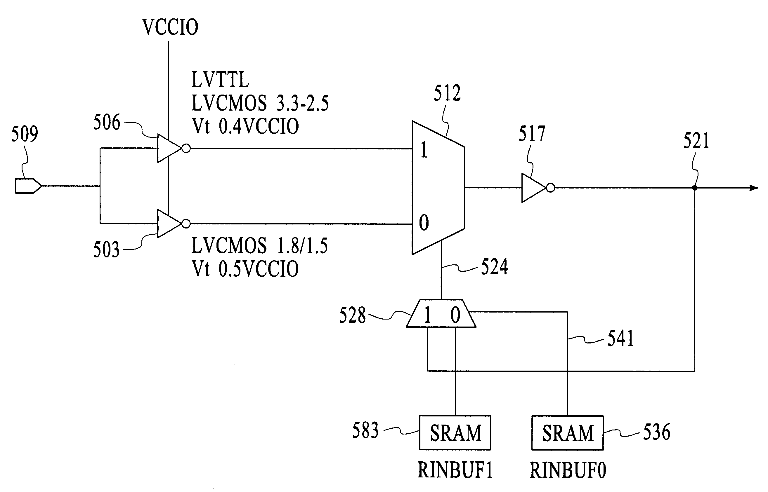
Input buffer with selectable threshold and hysteresis option
a buffer and selectable technology, applied in the field of integrated circuits, can solve the problems of false switching, large noise content caused by coupling, and noisy digital systems, and achieve the effect of adding a hysteresis option and sufficient hysteresis
- Summary
- Abstract
- Description
- Claims
- Application Information
AI Technical Summary
Benefits of technology
Problems solved by technology
Method used
Image

Examples
Embodiment Construction
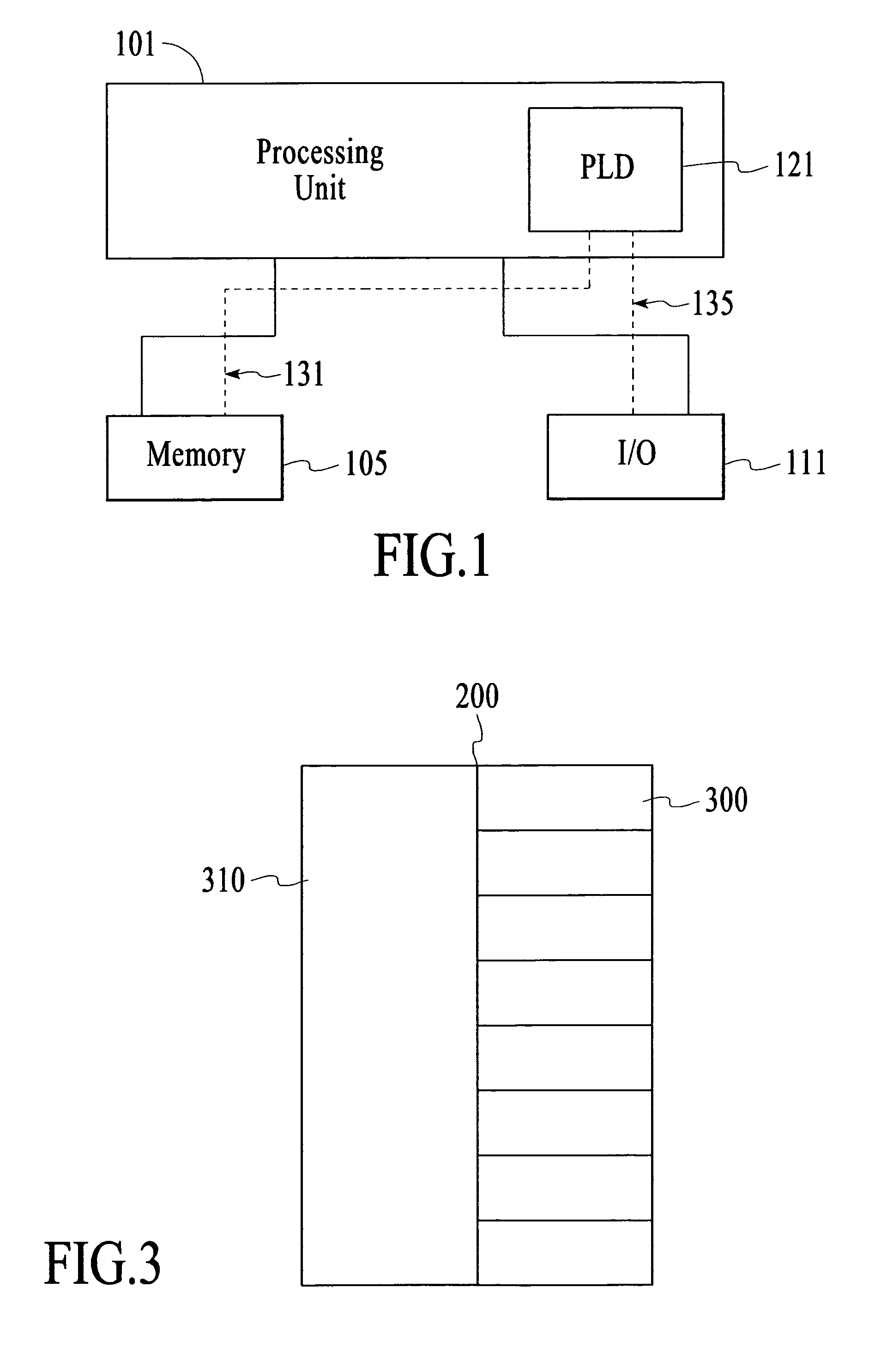
[0019]FIG. 1 shows a block diagram of a digital system, within which input and output interfaces consistent with the present invention may be embodied. The system may be provided on a single board, on multiple boards, or within multiple enclosures. Though embodiments of the present invention are useful in electronic and integrated circuits in general, they are particularly useful in programmable logic devices. FIG. 1 illustrates a system 101 in which such a programmable logic device 121 may be utilized. Programmable logic devices or programmable logic integrated circuits are sometimes referred to as a PALs, PLAs, FPLAs, PLDs, CPLDs, EPLDs, EEPLDs, LCAs, or FPGAs and are well-known integrated circuits that provide the advantages of fixed integrated circuits with the flexibility of custom integrated circuits. Such devices allow a user to electrically program standard, off-the-shelf logic elements to meet a user's specific needs. Examples of current programmable logic devices are repre...
PUM
 Abstract
Description
Claims
Application Information