Integrated cooling duct for resin-encapsulated distribution transformer coils

a transformer coil and resin-encapsulated technology, applied in the field of electric transformers, can solve the problems of heat dissipation, inefficiency and potential damage, and the damage of spacers, and achieve the effect of preventing epoxy leakag

Inactive Publication Date: 2006-04-04
HITACHI ENERGY SWITZERLAND AG
View PDF32 Cites 52 Cited by
  • Summary
  • Abstract
  • Description
  • Claims
  • Application Information

AI Technical Summary

Benefits of technology

[0008]The present invention also includes a method of manufacturing a transformer coil encapsulated in a casting resin, with integrated resinous cooling ducts. A disposable inner mold is placed over an annular form, or support, on a mandrel shaft. A continuous coil of conductive material then is wound around the inner mold, while the pre-cut cooling ducts are interspaced between successive layers of the coil....

Problems solved by technology

Epoxy provides excellent protection for the transformer coil; however, it can create a problem with heat dissipation.
Regardless of the type of spacers used, the process can result in inefficiencies and the potential for damage, as the spacers must be forcibly removed with pulling devices or overhead cranes.
The spacers quite often are damaged while being removed, thus requiring repair or replacement.
Duct spacers, such as aluminum, can also cause damage to the coil in a variety of way...

Method used


Image

  • Integrated cooling duct for resin-encapsulated distribution transformer coils
  • Integrated cooling duct for resin-encapsulated distribution transformer coils
  • Integrated cooling duct for resin-encapsulated distribution transformer coils

Examples


Embodiment Construction

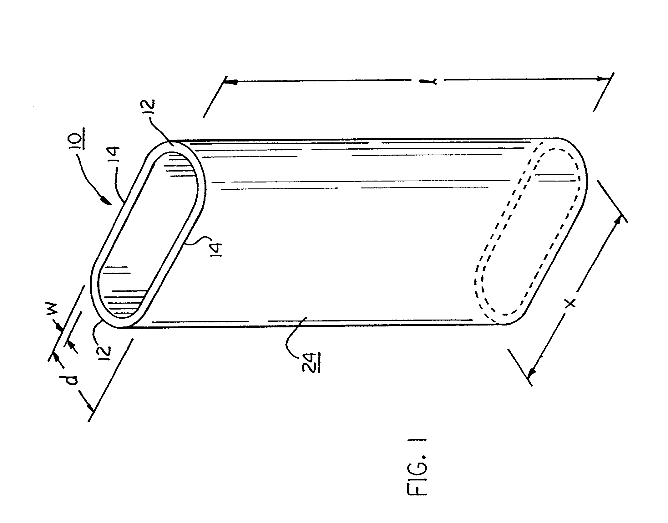
[0017]As shown in FIG. 1, one aspect of the present invention is directed to a tube 10, for permanent installation as a cooling duct in a resin-encapsulated transformer coil. The tube has a cross-section that is generally elliptical, with rounded ends 12 and substantially straight sides 14. While the precise geometry of the tube is not critical to the present invention, it has been found that, when the linear dimension, x, of the tube is about three times the width, d, of the tube, the tube is optimally shaped for placement between the alternating layers of a wound coil. With these relative dimensions, the tube is also structurally optimized, and provides optimal heat transfer from resin-encapsulated systems, such as transformer coils. By way of example, one tube constructed according to the present invention has a linear dimension, x, of about 2.7 inches, a width, d, of about 0.9 inches, and a wall thickness, w, of about 0.1 inches. As will be described in greater detail below, the...


PUM

PropertyMeasurementUnit
Lengthaaaaaaaaaa
Electrical conductoraaaaaaaaaa

Abstract

A dry-type, resin-encapsulated transformer coil that includes multiple layers formed from a length of conductive material, and multiple cooling ducts that are formed of thermoplastic material and spaced between the layers of conductive material. The thermoplastic material forming the cooling ducts and the resin that encapsulates the multiple layers of conductive material are thermally and electrically compatible.

Description

FIELD OF THE INVENTION[0001]The present invention relates to the field of electrical transformers, and, more particularly to a dry-type, resin-encapsulated transformer coil having permanently installed cooling ducts that are thermally and electrically compatible with the resin encapsulating the coil.BACKGROUND OF THE INVENTION[0002]The design and reliability of transformer coils has steadily improved over the last several decades. Today, dry-type encapsulated transformer coils are either coated with resins or cast in epoxy resins using vacuum chambers and gelling ovens. Epoxy provides excellent protection for the transformer coil; however, it can create a problem with heat dissipation. To dissipate the heat from around the coil, cooling ducts are formed at predetermined positions within the coil to aid cooling, improve the operating efficiency of the coil, and extend the operational life of the coil.[0003]The conventional method of creating cooling duct passages is to place solid sp...

Claims


Application Information

Patent Timeline
IPC IPC(8): H01F27/08H01F27/32H01F41/12
CPCH01F27/085H01F27/322H01F27/327H01F41/127H01F2027/328Y10T29/49071Y10T29/49224Y10T29/49073Y10T29/4902Y10T29/49078
Inventor LANOUE, THOMAS J.MITCHELL, MICHAEL J.PAULEY, JR., WILLIAM E.SARVER, CHARLIE H.
Owner HITACHI ENERGY SWITZERLAND AG
Why Eureka
Try Eureka