Peripheral monitor for monitoring periphery of vehicle

a technology for periphery monitoring and peripheral monitors, applied in the direction of instruments, transportation and packaging, using reradiation, etc., can solve the problems of fluctuation of characteristics and variability of reflection waves

Inactive Publication Date: 2006-04-04
MITSUBISHI ELECTRIC CORP
View PDF13 Cites 130 Cited by
  • Summary
  • Abstract
  • Description
  • Claims
  • Application Information

AI Technical Summary

Problems solved by technology

Further, when sticking any foreign matter such as water drop, water film or mud onto the cover surface, quantity of the reflected waves varies, and there arise a possibility of fluctuation in characteristics.

Method used


Image

  • Peripheral monitor for monitoring periphery of vehicle
  • Peripheral monitor for monitoring periphery of vehicle
  • Peripheral monitor for monitoring periphery of vehicle

Examples


embodiment 1

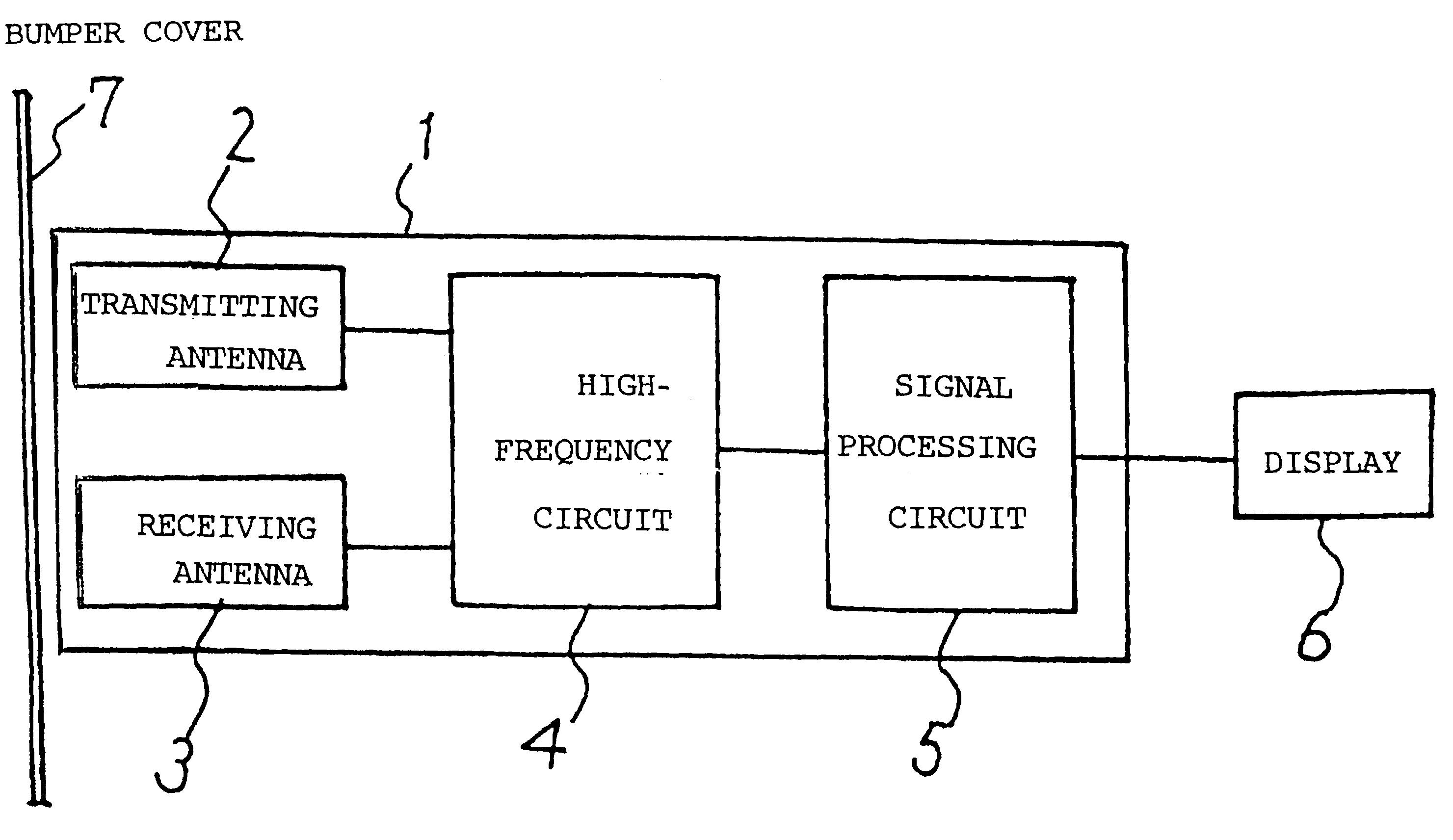
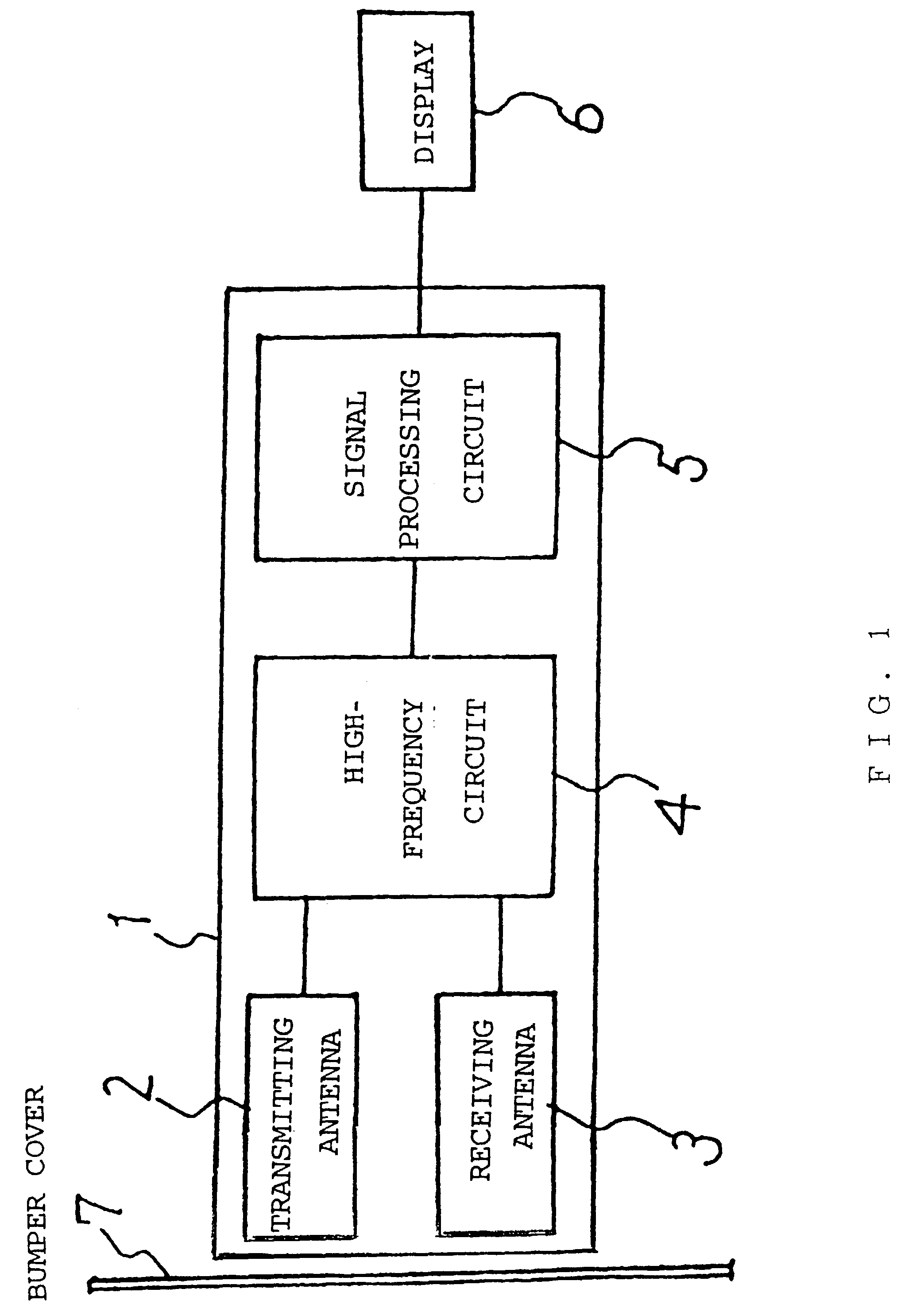
[0030]FIG. 1 is a diagram showing a constitution of a peripheral monitor for monitoring periphery of a vehicle according to Embodiment 1 of the present invention. Referring to FIG. 1, a peripheral monitor 1 for monitoring periphery of a vehicle includes a transmitting antenna 2 for transmitting radio waves transmitting through a cover described below (more specifically a bumper or a bumper cover 7, hereinafter collectively referred to as cover), a receiving antenna 3 for receiving radio waves reflected from any object existing in the periphery of the vehicle via the bumper cover, a high-frequency circuit 4 provided with a transmitting circuit for transmitting radio waves and a receiving circuit for receiving radio waves, and a signal processing circuit 5 for processing data of received signals and commanding a transmission frequency. In this peripheral monitor, any result obtained by signal processing is displayed on a display 6 or the like, whereby information is provided to a driv...

embodiment 2

[0045]In the description of the foregoing Embodiment 1, every measurement (transmission and reception of pulses and analysis of the data) in the monitoring mode takes several tens microseconds (for example, 50 microseconds).

[0046]Repeating the measurement continuously carries out monitoring apparently, and the reflection level is measured for every transmission. For example, a reflection from an object to be monitored such as other vehicle is discriminated from that from the bumper cover on the basis of a difference in reflection time. In this manner, level of the reflection from the bumper is measured in every measurement in this way. If it is judged that the reflection level is above a predetermined level, the operation controller 53 automatically gives a command to switch to the adjusting mode, and measurement is carried out for the optimum frequency as described in the foregoing Embodiment 1. Thereafter, the monitoring mode with the optimum frequency is automatically continued. ...

embodiment 3

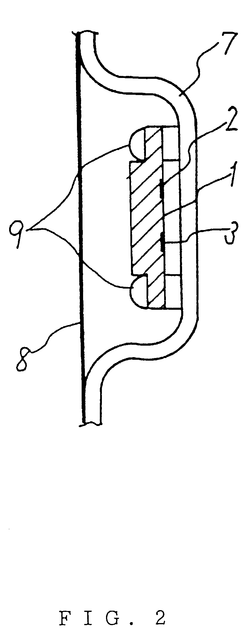
[0047]It is sometimes the case that during driving the vehicle, water drop, water film or dirt sticking onto the surface of the bumper cover 7 due to rain, snow, or splashes of mud. Under such a situation, there is a likelihood of variation in reflection from the bumper cover. Described hereunder is the case where there is nothing sticking onto the bumper cover and the case where there is any foreign matter such as water drop, water film or dirt sticking onto the surface of the bumper cover. Regarding these two cases, variation in quantity of radio waves reflected from the bumper cover and that in quantity of radio waves transmitting through the bumper cover with respect to variation in transmission frequency are going to be described with reference to FIGS. 7 to 16. FIGS. 7 and 8 show variation in quantity of radio waves reflected from the bumper cover and that in quantity of radio waves transmitting through the bumper cover in the case that any water drop sticks onto the bumper co...


PUM


Abstract

The invention solves a problem of fluctuation in performance in the conventional peripheral monitor for monitoring periphery of a vehicle that measures a distance to other vehicle or any other object by transmitting radio waves and informs a driver of the distance due to variation in environmental conditions such as water drop sticking onto the cover. A peripheral monitor 1 including a transmission antenna 2 for radiating transmission waves through the cover, a receiving antenna 3 for receiving reflected waves through the cover, and a data processor for measuring a distance to any object are disposed together in a cover 7. A transmission frequency at which reflected wave quantity is minimized is detected by detecting a first reflected signal level from the cover 7, and this frequency is a command to a variable frequency oscillator to conduct a transmission at this frequency at all times.

Description

BACKGROUND OF THE INVENTION[0001]1. Field of the Invention[0002]The present invention relates to a peripheral monitor for monitoring periphery of a vehicle that is used to prevent the vehicle running on a road from running into and colliding with any obstacle by measuring a distance to the obstacle existing in the periphery of the vehicle and warning the driver.[0003]2. Description of Related Art[0004]Hitherto, a peripheral monitor for monitoring periphery of a vehicle is mounted on the inside of a bumper cover of the vehicle. For mounting such a peripheral monitor, relative position and angle between an antenna and the bumper are gradually changed while being monitored on the basis of amplification degree of an amplifier for amplifying strength of signals received by the antenna, and the antenna is fixed at a position and angle where amount of signal reflected from the bumper cover is the smallest in quantity. (See the Japanese Patent Publication (unexamined) No. 2002-071788 (parag...

Claims


Application Information

Patent Timeline
Patent Type & Authority Patents(United States)
IPC IPC(8): B60Q1/00G01S7/03G01S7/282B60R11/02G01S7/40G01S13/93G08G1/16
CPCG01S7/4008G01S2007/4039G01S2013/9389G01S2013/93275G01S7/4039
Inventor KODAMA, KATSUHISA
Owner MITSUBISHI ELECTRIC CORP
Why Eureka
Try Eureka