Reflector for a mobile radio antenna

a mobile radio antenna and reflector technology, applied in the field of reflectors, can solve the problems of large number of different parts and the major assembly effort associated with them, disadvantages of polarised antenna unit combinations, comparatively high production costs, etc., and achieve the effect of improving mechanical reliability, avoiding undesirable intermodulation products, and adjusting production tolerances

Inactive Publication Date: 2006-04-04
TELEFON AB LM ERICSSON (PUBL)
View PDF40 Cites 21 Cited by
  • Summary
  • Abstract
  • Description
  • Claims
  • Application Information

AI Technical Summary

Benefits of technology

[0006]The illustrative non-limiting exemplary technology described herein provides an improved capability to produce antennas with high quality characteristics, by means of which it is furthermore intended to be possible to produce antennas of different physical sizes with comparatively little complexity and to a high quality standard.
[0008]At the same time, the exemplary illustrative non-limiting antenna or reflector configuration described herein makes it possible to considerably reduce the number of contact points. In turn, this makes it possible to reduce the large number of different parts and the assembly effort, with a high degree of functional integration as well.
[0018]One exemplary illustrative non-limiting implementation therefore provides for the corresponding end walls to be appropriately matched for joining together at least two reflector modules. For this purpose, they preferably may have attachment points which are offset with respect to one another in two planes. This makes it possible firstly to transmit and to absorb comparatively large moments, while at the same time providing functionally reliable electrical contact points. An electrically conductive contact can be made between the two reflector modules in the area of their end walls that are joined together. Or, they can also be connected to one another without any electrically conductive connection, for example by inserting an insulating intermediate layer, for example a plastic layer or some other dielectric, between them. In some circumstances, a damper material can also preferably be used for the intermediate joint for an insulating layer such as this, which means that the two reflector module halves may even oscillate to a certain extent with respect to one another, to a restricted extent, in a severe storm. This thus serves to improve mechanical reliability.
[0019]The offset plane of the attachment points, that has been mentioned, also serves to ensure that shape discrepancies are not additive at the connecting interface. If necessary, such phenomenon can be compensated for with comparatively few problems, in such a way that production tolerances can be compensated for. If, for optimization of the polar diagram of an antenna, it is necessary or desirable to attach additional metallic elements at specific points in the reflector, then, in one exemplary illustrative development, these additional elements may be used, for example, in the form of electrically conductive strips, webs etc., by means of separate holding devices. For example, electrically nonconductive holding devices can be preferably formed from plastic or from some other dielectric. They can be fitted to the existing intermediate webs or side boundary wall sections. In one exemplary illustrative implementation, between the holding devices, the metallic elements which have to be inserted in addition can then be hooked in. This capacitive anchoring then once again furthermore avoids undesirable intermodulation products.
[0020]One exemplary illustrative non-limiting implementation provides for a reflector module which has been produced using a casting, deep-drawing, thermoforming or stamping method. Alternatively, a milling method can be used. Further integrated parts, or parts of further components, which are required in particular in conjunction with an antenna can be provided, on the rear face of the reflector module, opposite the antenna element modules for example. This allows functional integration to be achieved in the reflector, associated with further significant advantages.

Problems solved by technology

However, this can result in a number of disadvantages.
For example, the large number of different parts and the major assembly effort associated with them can be disadvantageous.
Overall, these can result in comparatively high production costs.
Another possible disadvantage is the large number of contact points.
A large number of contact points can contribute to undesirable intermodulation products.
On the other hand, the antennas that are produced in this way generally have a restricted function and load capability since, particularly in the case of unsuitable material combinations or even if there are only a small number of bad contact points, it may not be possible to comply with the requirements relating to undesirable intermodulation products.
If a test run of the checked polar diagram of an antenna reveals problems, then it is also not necessarily immediately possible to state which contact points may have contributed to the deterioration in the intermodulation characteristics.
However, moving and undefined contacts should generally also not be used in order to avoid undesirable intermodulation problems.

Method used


Image

  • Reflector for a mobile radio antenna
  • Reflector for a mobile radio antenna
  • Reflector for a mobile radio antenna

Examples


Embodiment Construction

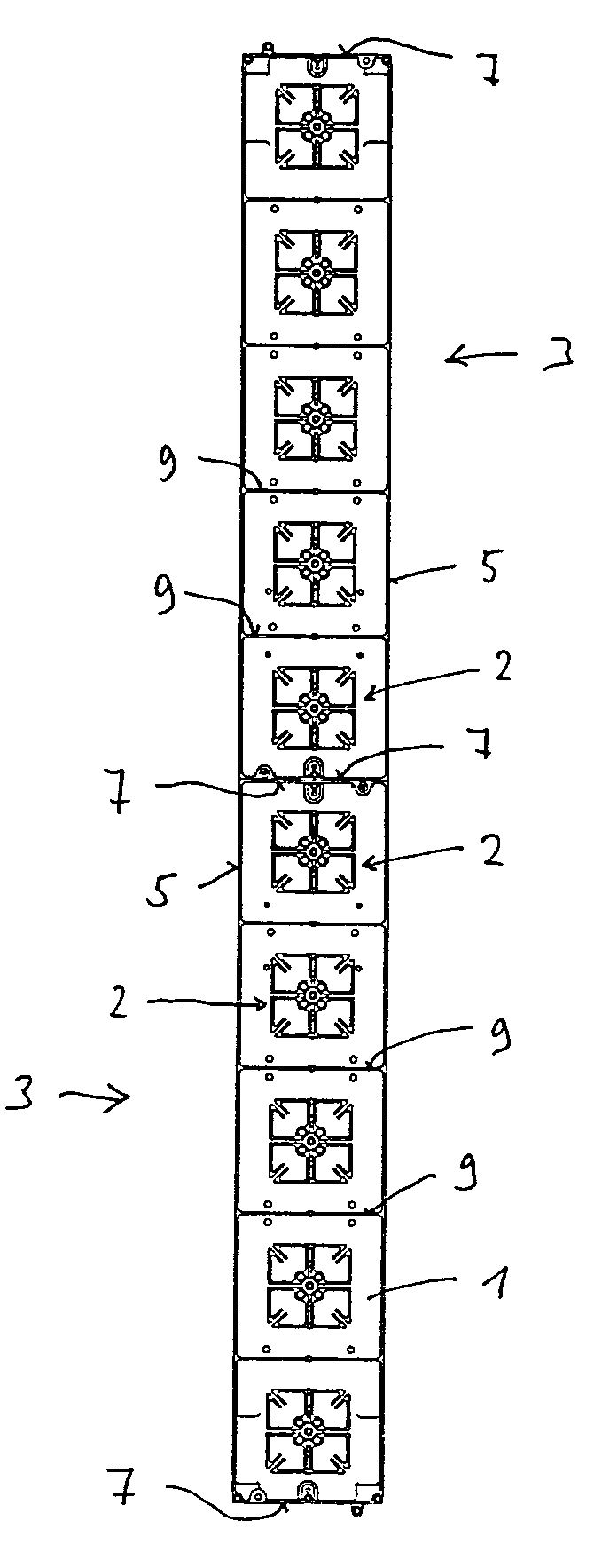
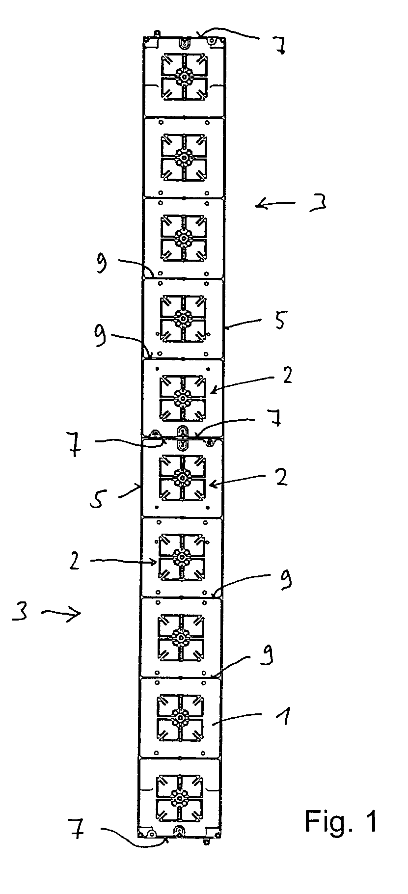
[0037]FIG. 1 shows a schematic plan view of an exemplary illustrative non-limiting reflector 1 which, in the illustrated exemplary arrangement, is formed from two reflector modules 3 whose end faces are joined together and in each of which four antenna element arrangements 2 are arranged one above the other in the vertical direction. The illustrated antenna element modules are, from the electrical point of view, modules in the form of cruciform antenna elements which radiate (e.g., can transmit and receive) two mutually perpendicular polarizations. These are preferably antenna elements arranged in an X-shape, in which the polarization planes are aligned at angles of plus 45° to minus 45° with respect to the horizontal and vertical. This specifically illustrated and indicated type of antenna element is known for example, from the prior application WO 00 / 39894. To this extent, reference is made to this prior application, which is included in the content of the present application. How...


PUM


Abstract

A reflector for a mobile radio antenna comprises at least two reflector modules which are or can be assembled. The reflector module is produced using a casting method, deep-drawing, thermoforming or stamping method, or using a milling method. Two integrally connected longitudinal face boundaries and at least one end transverse-face boundary may be provided. Two transverse-face boundaries whose ends are located offset with respect to one another can be provided. At least one transverse strut runs transversely with respect to the longitudinal face boundaries. A holding and / or attachment device is provided on the at least one end transverse-face boundary for attachment to a second reflector module, and can be used to fix the at least two reflector parts firmly to one another.

Description

FIELD[0001]The technology herein relates to a reflector, in particular for a mobile radio antenna.BACKGROUND AND SUMMARY[0002]Mobile radio antennas for mobile radio base stations are normally constructed such that two or more antenna element arrangements, which are located one above the other, are provided in the vertical direction in front of a reflector plane. These antenna element arrangements are formed, for example, from dipoles or patch antenna elements. These may be antenna element arrangements which can transmit and / or transmit and receive at the same time. They can operate only in one polarization or, for example, in two mutually perpendicular polarizations. The entire antenna arrangement may be designed for transmission in one band or in two or more frequency bands by using, for example, two or more antenna elements and antenna element groups which are suitable for the various frequency bands.[0003]Depending on the requirements, mobile radio antennas are generally used whi...

Claims


Application Information

Patent Timeline
Patent Type & Authority Patents(United States)
IPC IPC(8): H01Q1/42H01Q1/12H01Q1/24H01Q15/14H01Q15/16H01Q21/00H01Q21/24
CPCH01Q1/12H01Q1/246H01Q15/141H01Q21/24H01Q21/0025H01Q21/0087H01Q15/165H01Q1/42
Inventor GOTTL, MAXIMILIANBERGER, STEFAN
Owner TELEFON AB LM ERICSSON (PUBL)
Why Eureka
Try Eureka