Antenna system

a technology of antenna system and antenna technology, applied in the field of antenna system, can solve the problems of antenna system shutdown, existing antenna technology still does not offer a satisfactory solution to the looping effect, signal processing device is often saturated, etc., and achieves the effect of reducing side lobes, minimizing signal looping effect, and high directionality

Inactive Publication Date: 2006-04-04
BELLSOUTH INTPROP COR
View PDF16 Cites 232 Cited by
  • Summary
  • Abstract
  • Description
  • Claims
  • Application Information

AI Technical Summary

Benefits of technology

[0011]The present invention is an antenna system. The preferred embodiment of the invention includes a highly directional donor antenna. The donor antenna reduces side lobes and thereby minimizing signal looping effect with an adjacent antenna such as a coverage antenna in the antenna system. The donor antenna preferably has an antenna element enclosed in a reflective tube, the interior of which is lined with a reflective material that shields radio frequencies.

Problems solved by technology

As a result, the signal-processing device is often saturated by signals looping between the two antennas.
The saturation situation causes the antenna system to shut down.
However, the existing antenna technology still does not offer a satisfactory solution to the looping effect due to the following constraints.
First, the antennas cannot be separated more than twenty feet apart on a utility pole that is about 40 to 50 feet high.
Second, existing antennas are bulky and heavy, making them difficult to mount at higher locations.
Third, existing antennas have large cross-sections that are not desirable at higher altitudes due to wind loading.
Fourth, extending the height of the utility pole is not desirable due to cost, environmental, and aesthetic concerns.

Method used


Image

  • Antenna system
  • Antenna system
  • Antenna system

Examples


Embodiment Construction

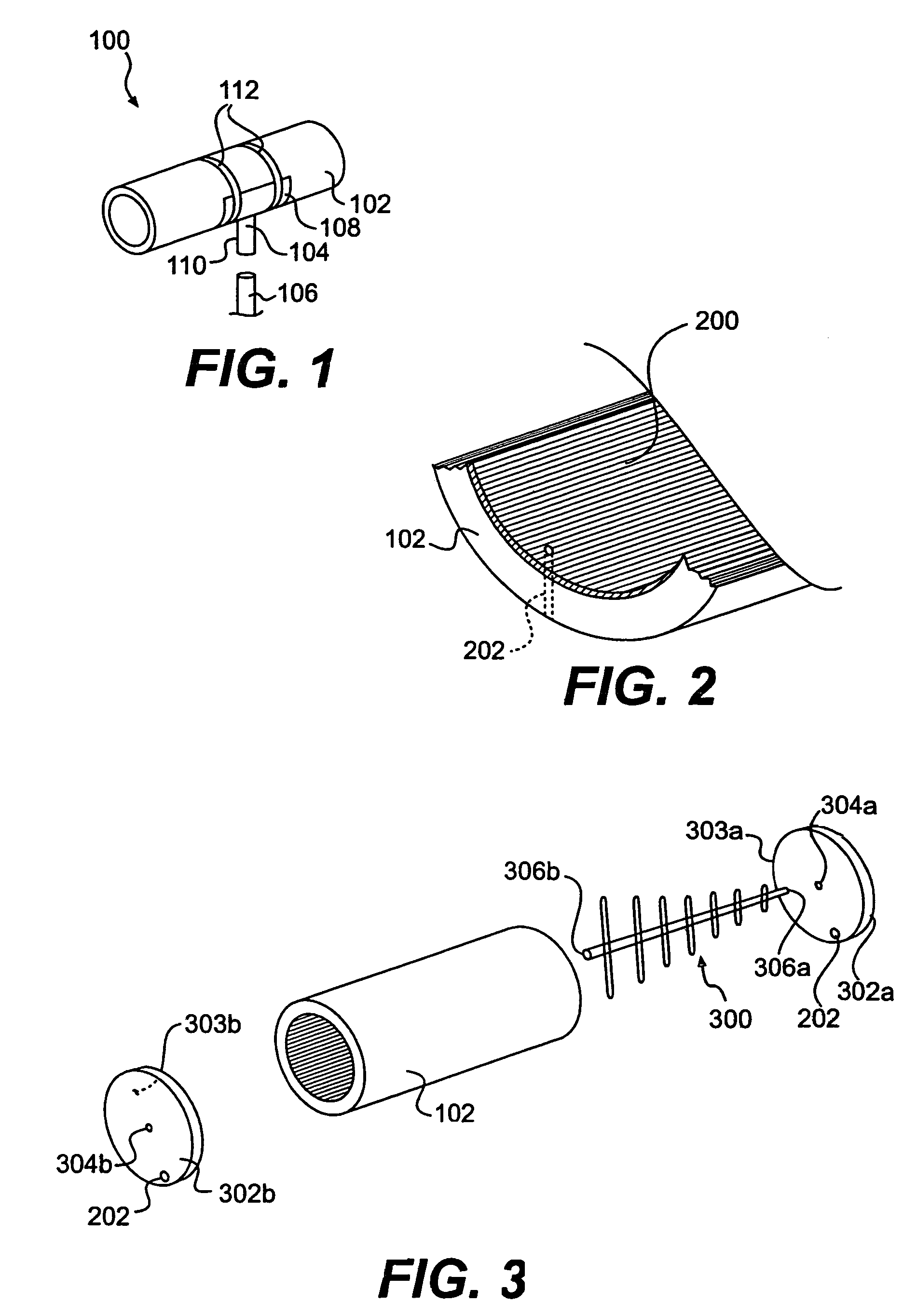
[0025]FIG. 1 is a schematic diagram of an isometric view of a preferred embodiment of the invention. Directional antenna 100 includes a reflective tube 102 and an adapter 104 that is designed to mate with a mast 106. In one embodiment, adapter 104 preferably includes a curved portion 108 that substantially corresponds to the curve of reflective tube 102, and a mating portion 110 that is designed to mate with mast 106. Adapter 104 can be attached to reflective tube 102 by a series of bands 112. Bands 112 are preferably made of a corrosion resistant material, for example, stainless steel. In another embodiment, adapter 104 and reflective tube 102 are formed as a single, monolithic unit. In other embodiments not shown in the drawings, reflective tube 102 may be any geometrical shape other than the cylindrical shape shown. For example, reflective tube 102 may be a block or an ellipsoid that is substantially tubular with a cross-section of a polygon and an oval, respectively.

[0026]Prefer...


PUM

PropertyMeasurementUnit
radiusaaaaaaaaaa
lengthaaaaaaaaaa
dielectric constantaaaaaaaaaa

Abstract

An antenna system that includes a directional antenna designed to reduce the occurrence of side lobes, thus reducing the possibility of interference with other radio frequencies is disclosed. The directional antenna includes an antenna member and a reflecting tube. The reflective tube is sleeved over the antenna member. The reflective serves to block unwanted radial side lobes. The directional antenna can also include provisions that assist in suspending the antenna member within the reflective tube.

Description

RELATED APPLICATION[0001]This is a divisional patent application of U.S. patent application Ser. No. 10 / 040,371, filed Jan. 9, 2002 now Pat. No. 6,724,350, which is a divisional application of application Ser. No. 09 / 604,753, filed on Jun. 28, 2000 and issued as U.S. Pat. No. 6,351,248 on Feb. 26, 2002. This application claims the benefits of the U.S. Ser. Nos. 09 / 604,753 and 10 / 040,371 applications, each of which is incorporated herein by reference in its entirety.BACKGROUND[0002]1. Field of the Invention[0003]The present invention relates to an antenna system.[0004]2. Background of the Invention[0005]An antenna is the heart of a wireless communications system. Antennas in transmitters convert electrical signals into airborne radio frequency (RF) waves, and in receivers they convert airborne waves into electrical signals. Without antennas there are no wireless communications.[0006]The size of an antenna depends on the radio frequency for which the antenna is designed. The higher th...

Claims


Application Information

Patent Timeline
Patent Type & Authority Patents(United States)
IPC IPC(8): H01Q9/34H01P11/00H01Q1/24H01Q1/42H01Q11/10H01Q19/10
CPCH01Q1/246H01Q1/42H01Q19/10H01Q11/10Y10T29/49016
Inventor HILL, DAVID A.
Owner BELLSOUTH INTPROP COR
Why Eureka
Try Eureka