Methods and systems to compensate for a stitching disturbance of a printed pattern in a maskless lithography system utilizing overlap without an explicit attenuation

a maskless lithography and pattern technology, applied in the field of printing patterns, can solve the problems of optical effects, stitching errors in printed patterns, and stitching errors in printed patterns, and achieve the effects of reducing the probability of optical effects causing stitching errors and reducing the probability of optical effects

Inactive Publication Date: 2006-04-04
ASML HLDG NV
View PDF8 Cites 24 Cited by
  • Summary
  • Abstract
  • Description
  • Claims
  • Application Information

AI Technical Summary

Problems solved by technology

Stitching errors in the printed pattern occur near these boundaries between adjacent exposure zones due to both geometrical misalignments of the exposures and disturbances due to other optical phenomena.
Generally, stitching errors occur in printed patterns due to spatial misalignment of the exposure zone on the wafer from its expected position.
Optical effects may also create stitching errors, even in cases where the alignment may be perfect.
Even a small spatial misalignment of the shots, in the case of a spatial misalignment, may result in a significant perturbation of the printed pattern near the stitching line.
Since two adjacent exposure zones are exposed at different times, the exposures are effectively incoherent, thus creating the unwanted optical effects.

Method used


Image

  • Methods and systems to compensate for a stitching disturbance of a printed pattern in a maskless lithography system utilizing overlap without an explicit attenuation
  • Methods and systems to compensate for a stitching disturbance of a printed pattern in a maskless lithography system utilizing overlap without an explicit attenuation
  • Methods and systems to compensate for a stitching disturbance of a printed pattern in a maskless lithography system utilizing overlap without an explicit attenuation

Examples


Embodiment Construction

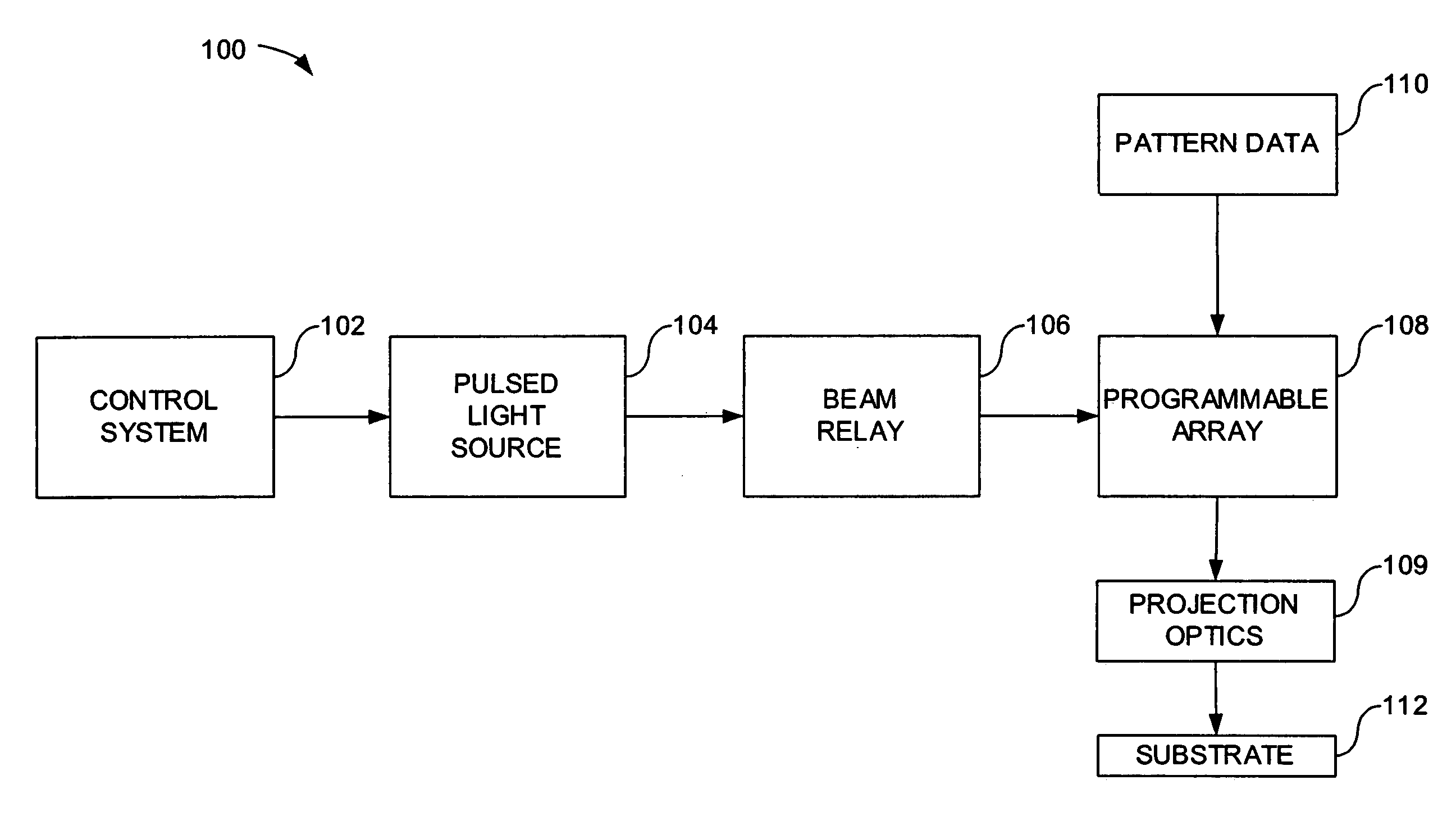
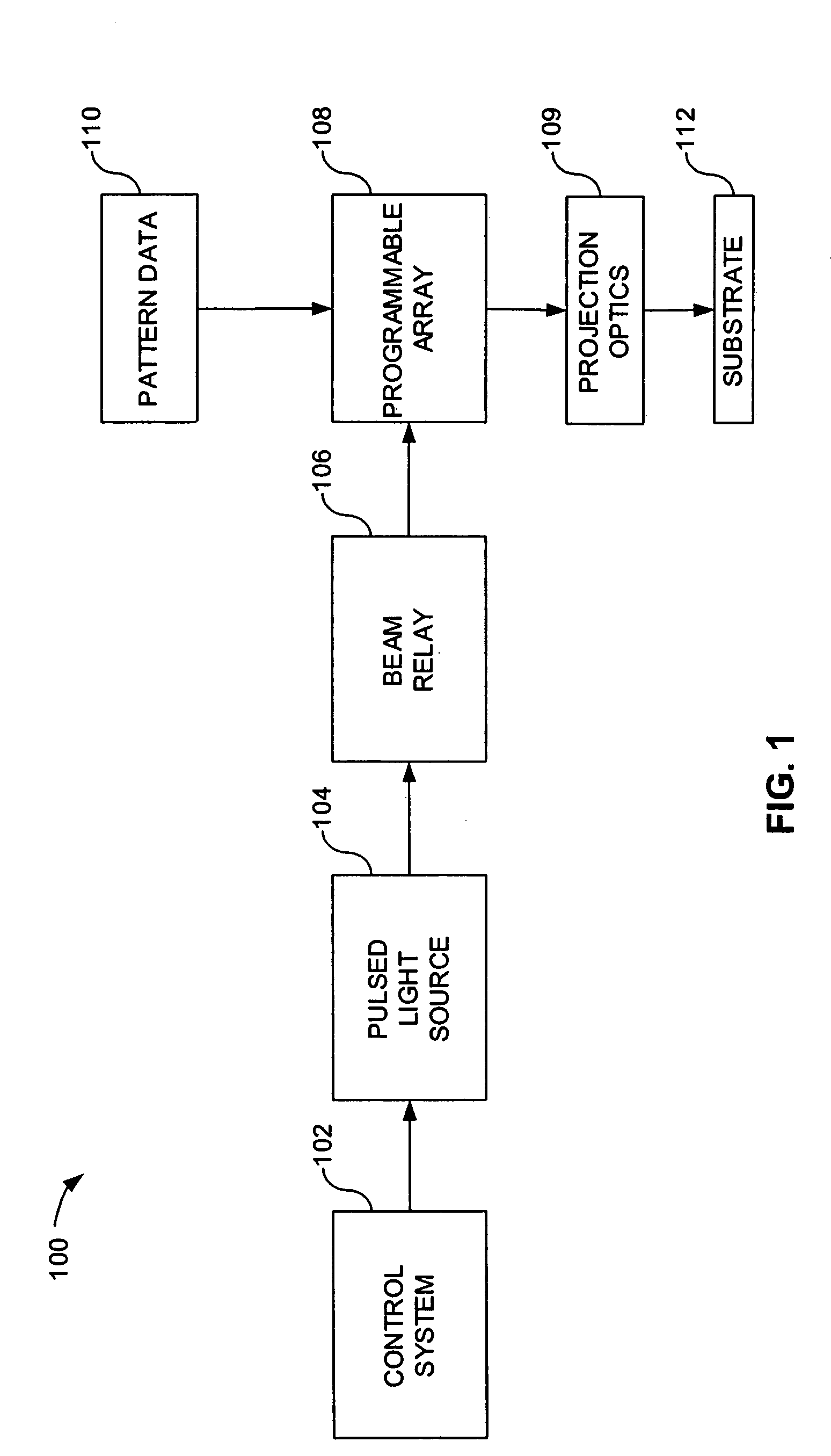
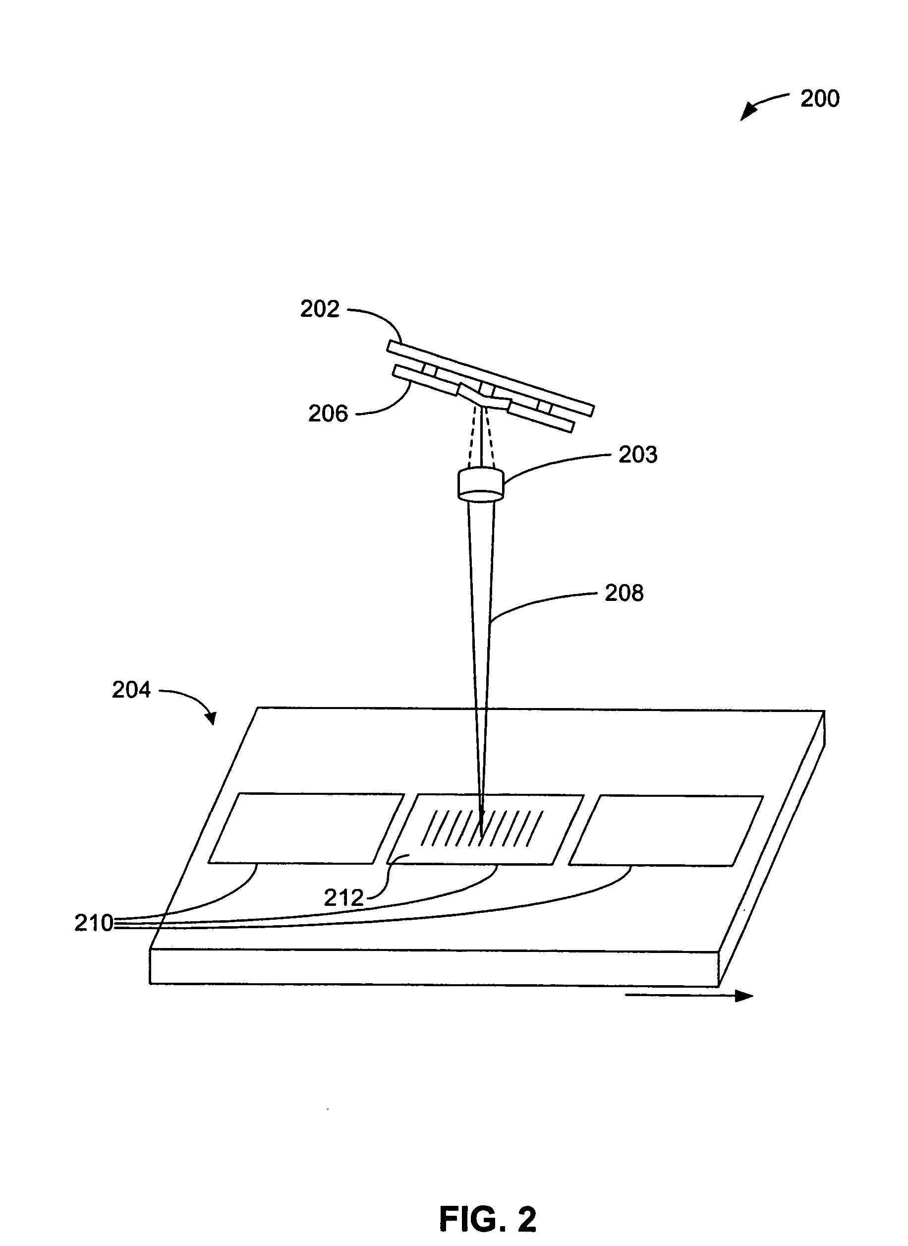
[0024]The following detailed description of the present invention refers to the accompanying drawings that illustrate exemplary embodiments consistent with this invention. Other embodiments are possible, and modifications may be made to the embodiments within the spirit and scope of the invention. Therefore, the following detailed description is not meant to limit the invention. Rather, the scope of the invention is defined by the appended claims.

[0025]It would be apparent to one skilled in the art that the present invention, as described below, may be implemented in many different embodiments of hardware, software, firmware, and / or the entities illustrated in the drawings. Any actual software code with the specialized, controlled hardware to implement the present invention is not limiting of the present invention. Thus, the operation and behavior of the present invention will be described with the understanding that modifications and variations of the embodiments are possible, give...


PUM

PropertyMeasurementUnit
light wavelengthaaaaaaaaaa
widthaaaaaaaaaa
widthaaaaaaaaaa

Abstract

A method and system are provided for printing a pattern on a photosensitive surface using a maskless lithography system including a spatial light modulator (SLM). The method includes defining two or more exposure areas within a predetermined region of the surface, each area corresponding to selected pixels of the SLM. An overlap region is formed between the two or more exposure areas, the overlapping region being defined by respective overlapping edges of the exposure areas, the overlapping edges corresponding to overlapping pairs of the selected pixels from each area. The pixels within each pair are alternately activated such that only one of the pixels within the pair is used to produce the pattern.

Description

BACKGROUND OF THE INVENTION[0001]1. Field of the Invention[0002]The present invention generally relates to printing patterns on photosensitive surfaces.[0003]2. Related Art[0004]A printed pattern in a generic, maskless lithography tool is formed from a sequence of exposures, or shots. Each shot results from an image of a spatial light modulator (SLM) array being projected onto the surface of a photosensitive surface, such as a wafer substrate. This results in deposition of a dose, or a quantity of irradiation from a light source, within a certain exposure zone on this surface. Exposure zones are created when the substrate surface is illuminated by flashes of light from the light source. When the pattern extends beyond the boundaries of exposures of a single SLM, the exposures are stitched together along adjacent boundaries to form a completed pattern.[0005]Stitching errors in the printed pattern occur near these boundaries between adjacent exposure zones due to both geometrical misa...

Claims


Application Information

Patent Timeline
Patent Type & Authority Patents(United States)
IPC IPC(8): G03B27/42G03B27/54G03B27/72G03F7/20H01L21/027
CPCG03B27/54G03F7/70475G03F7/70291
Inventor LATYPOV, AZATVAN DER MAST, KAREL
Owner ASML HLDG NV
Why Eureka
Try Eureka