
Air bearing designs to reduce external van der waals and electrostatic forces

a technology of air bearings and electrostatic forces, applied in the direction of maintaining the alignment of the head carrier, recording information storage, instruments, etc., can solve the problems of affecting the performance of the resulting air bearing, the design of a suitable air bearing surface requires substantial effort, and the bearing to collapse. , to achieve the effect of reducing van der waals and electrostatic forces

Inactive Publication Date: 2006-04-04
WESTERN DIGITAL TECH INC
View PDF11 Cites 11 Cited by
  • Summary
  • Abstract
  • Description
  • Claims
  • Application Information

AI Technical Summary

Benefits of technology

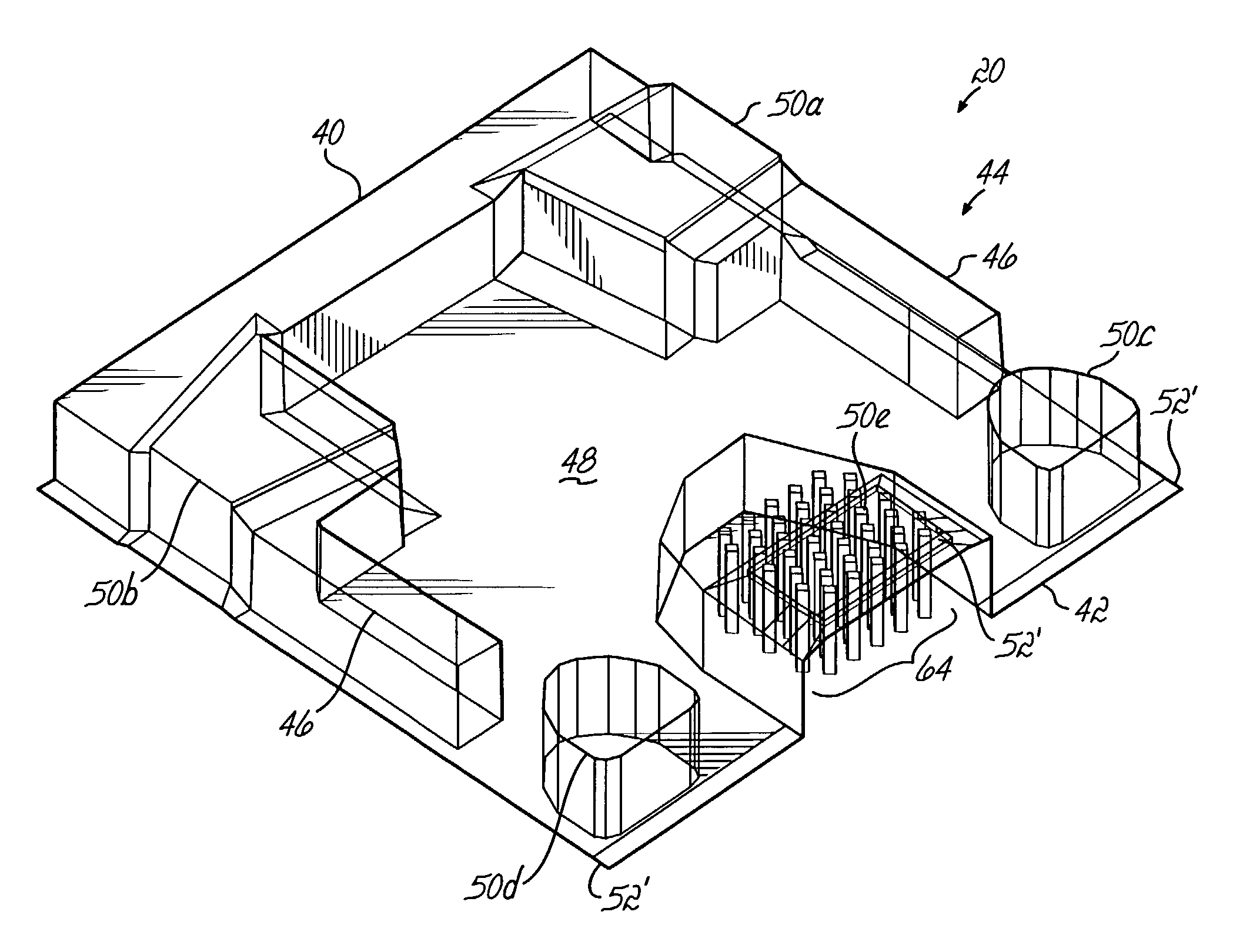
[0008]The invention addresses these and other problems associated with the prior art by providing a disk drive, a slider for use therein, and a method that incorporate one or more interior cavities within an air bearing surface of a slider to reduce van der Waals and electrostatic forces between the slider and a rotatable disk of recordable media.
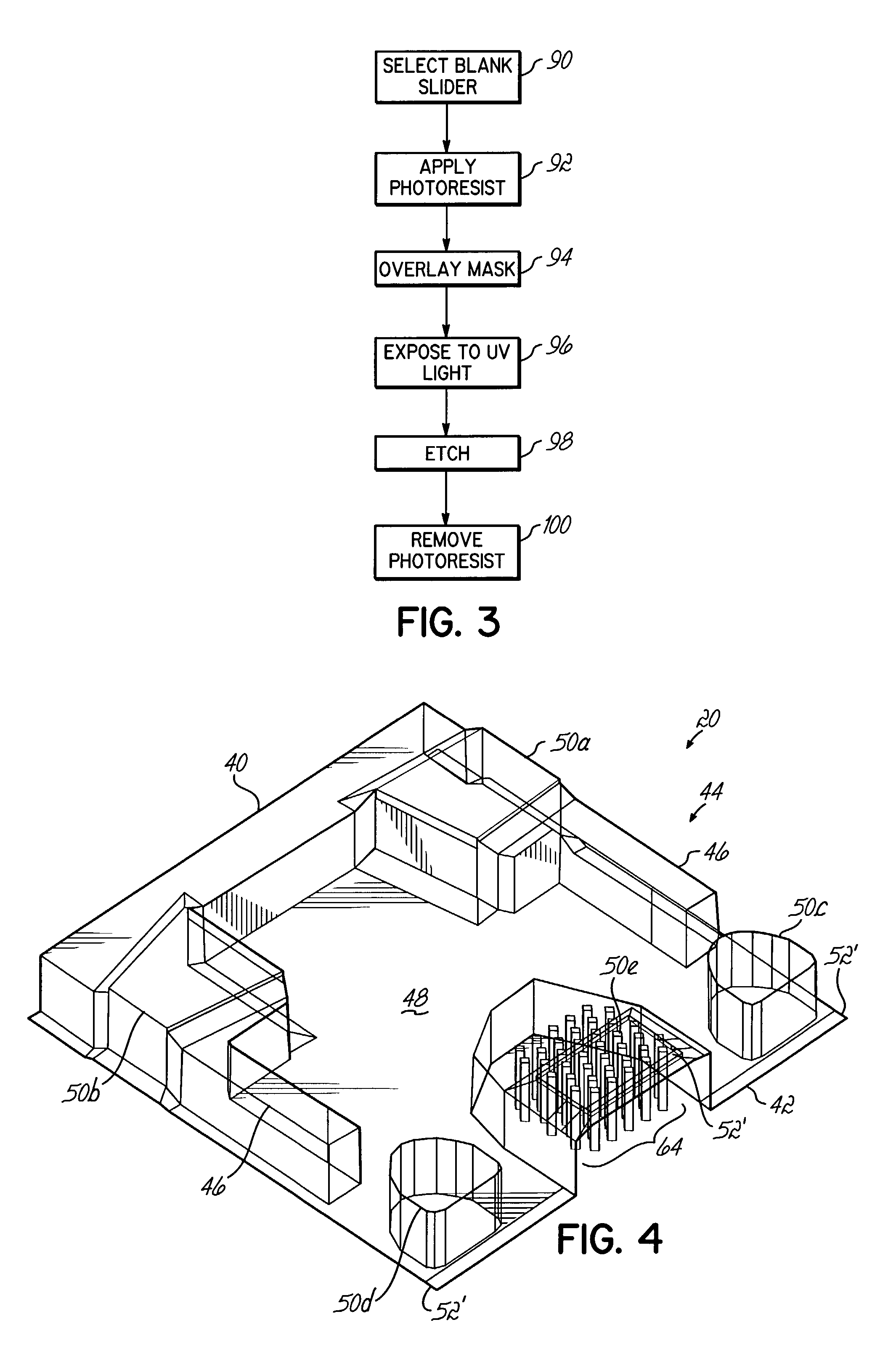
[0009]In one embodiment consistent with the invention, the cavities form a pattern of diamond shaped columns in a trailing edge pad. In another embodiment consistent with the present invention, the cavities form a pattern of chevron shaped columns. Irrespective of the design used, by incorporating the cavities into the interior of an air bearing surface, the effects of van der Waals and electrostatic forces may often be reduced without an alteration of the profile of the surface.

Problems solved by technology

At fly heights of a few nanometers, such forces can potentially disrupt the balance of pressures created by an air bearing surface, causing the resulting air bearing to collapse, and allowing the slider to come into contact with the disk.
However, both of these approaches require modifying the profile of the air bearing surface, and thus affect the performance of the resulting air bearing.
The design of a suitable air bearing surface requires substantial effort, and must accommodate a large number of factors to achieve reliable steady state fly heights of only a few nanometers.
Thus, the aforementioned approaches to reducing the effects of external forces introduce additional considerations to the air bearing surface design, and constrain air bearing designers in their ability to manipulate the pressures created by the rails and the recessed portion on the air bearing, thereby impacting the steady state fly height profile.

Method used


Image

  • Air bearing designs to reduce external van der waals and electrostatic forces
  • Air bearing designs to reduce external van der waals and electrostatic forces
  • Air bearing designs to reduce external van der waals and electrostatic forces

Examples


Embodiment Construction

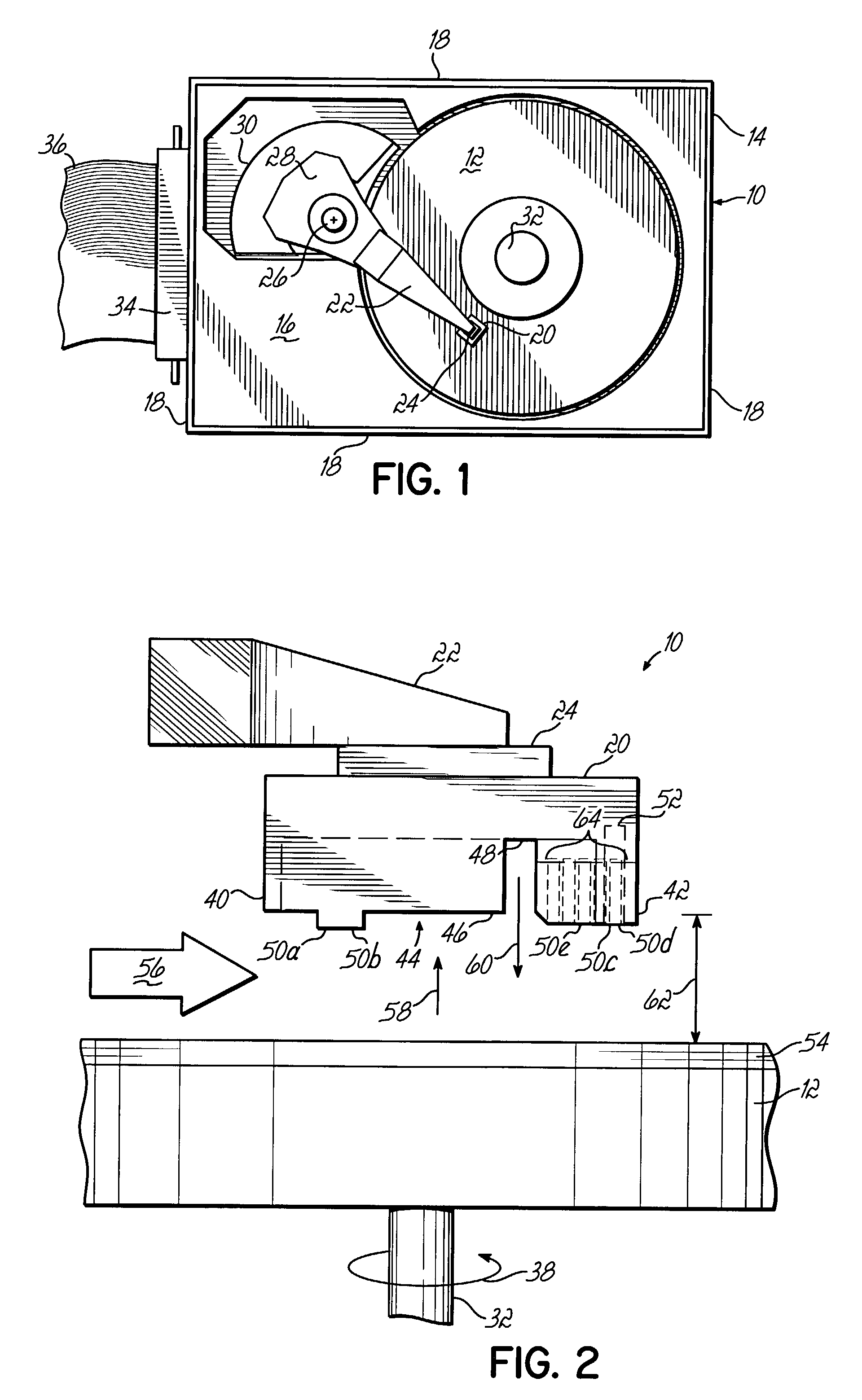
[0018]Referring to FIG. 1, a sectional view of an embodiment 10 of a disk drive incorporating features of the present invention is shown. Disk drive 10 is a rotary disk drive type using a magnetic disk media 12. The storage capacity of disk drive 10 is, in part, determined by the areal density of data stored on the recordable magnetic media disk 12.

[0019]Disk drive 10 comprises a housing 14 to which other components of the disk drive 10 are mounted. Housing 14 may include a bottom 16, sidewalls 18, and a top (not shown). A read / write head 52 (see FIG. 2) is disposed within a slider 20 having an air bearing surface 44 (see FIGS. 2, 4 and 5) and which is coupled proximate the end of an actuator 22 using a gimbal 24. Actuator 22 rotates about a pivot point 26 under the action of a voice coil 28 of a motor 30 to position read / write head 52 over a predetermined track on disk 12. The read / write head 52 within slider 20 interacts with disk 12, which is mounted on a rotating spindle 32 and ...


PUM

PropertyMeasurementUnit
electrostatic forcesaaaaaaaaaa
pressureaaaaaaaaaa
pressuresaaaaaaaaaa

Abstract

A slider for a disk drive has an air bearing surface that opposes a rotatable disk of recordable media. The air bearing surface includes one or more interior cavities to reduce van der Waals and electrostatic forces that attract the slider to the disk.

Description

FIELD OF THE INVENTION[0001]The present invention relates generally to data storage devices, and more particularly to disk drives of the type including a slider having an air bearing surface.BACKGROUND OF THE INVENTION[0002]A principal part of any computer system is a data storage device. A disk drive is a typical data storage device. A disk drive generally includes at least one disk of magnetic storage material mounted on a motor shaft or spindle, an actuator that locates a read / write head radially over the disk, and circuitry that is used to read and write data from the disk using the read / write head. A disk drive may also include a controller that interfaces with the computer system while controlling the operation of the disk drive.[0003]The read / write head is typically housed in a “slider.” A slider has a lower surface known as an air bearing surface that opposes the surface of a disk in use. An air bearing surface typically includes rails that extend generally tangential to the...

Claims


Application Information

Patent Timeline
Patent Type & Authority Patents(United States)
IPC IPC(8): G11B21/21G11B17/32G11B5/60
CPCG11B5/6005G11B5/6082
Inventor CRONE, ROBERT MICHAELSMITH, GORDON JAMESTANG, WING TSANG
Owner WESTERN DIGITAL TECH INC
Learn More