
Method and apparatus for determining block match quality

a technology of block match quality and apparatus, applied in the field of motion estimation, can solve the problems of inefficiency of compression, poor quality, and prohibitive fsm

Active Publication Date: 2006-04-04
GOOGLE TECH HLDG LLC
View PDF9 Cites 28 Cited by
  • Summary
  • Abstract
  • Description
  • Claims
  • Application Information

AI Technical Summary

Benefits of technology

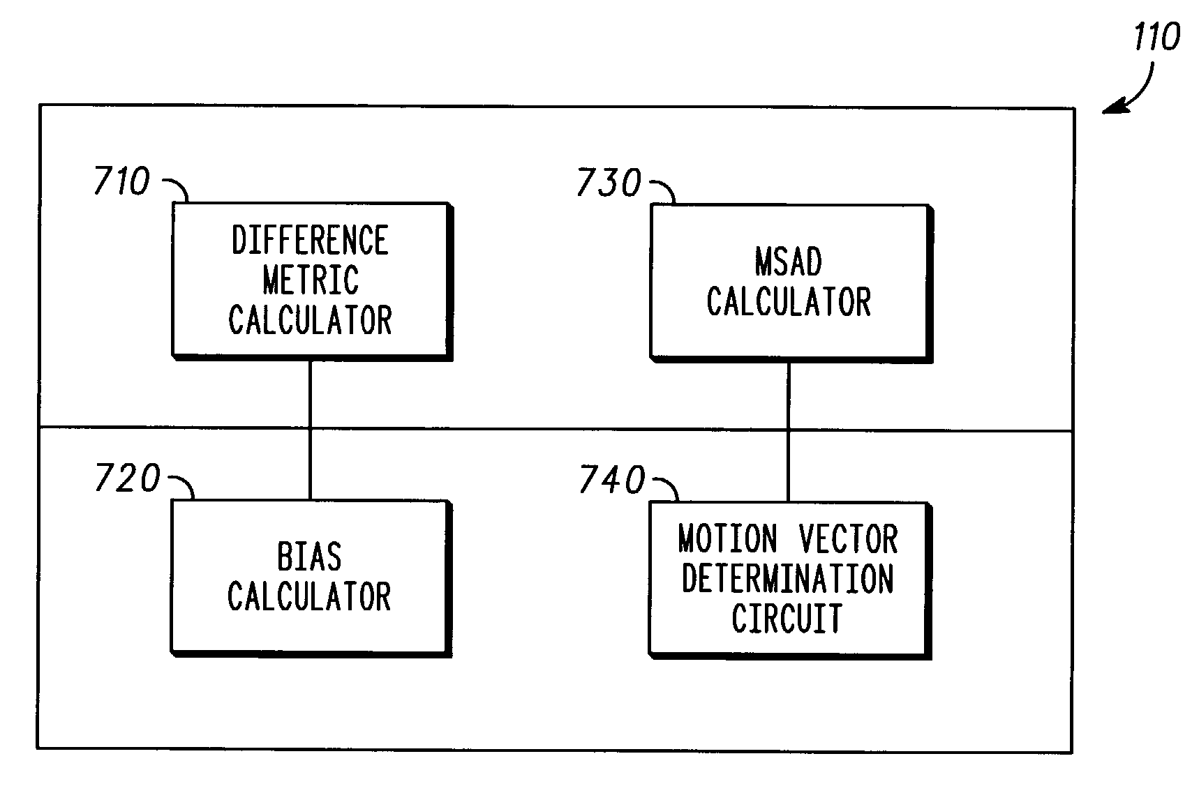
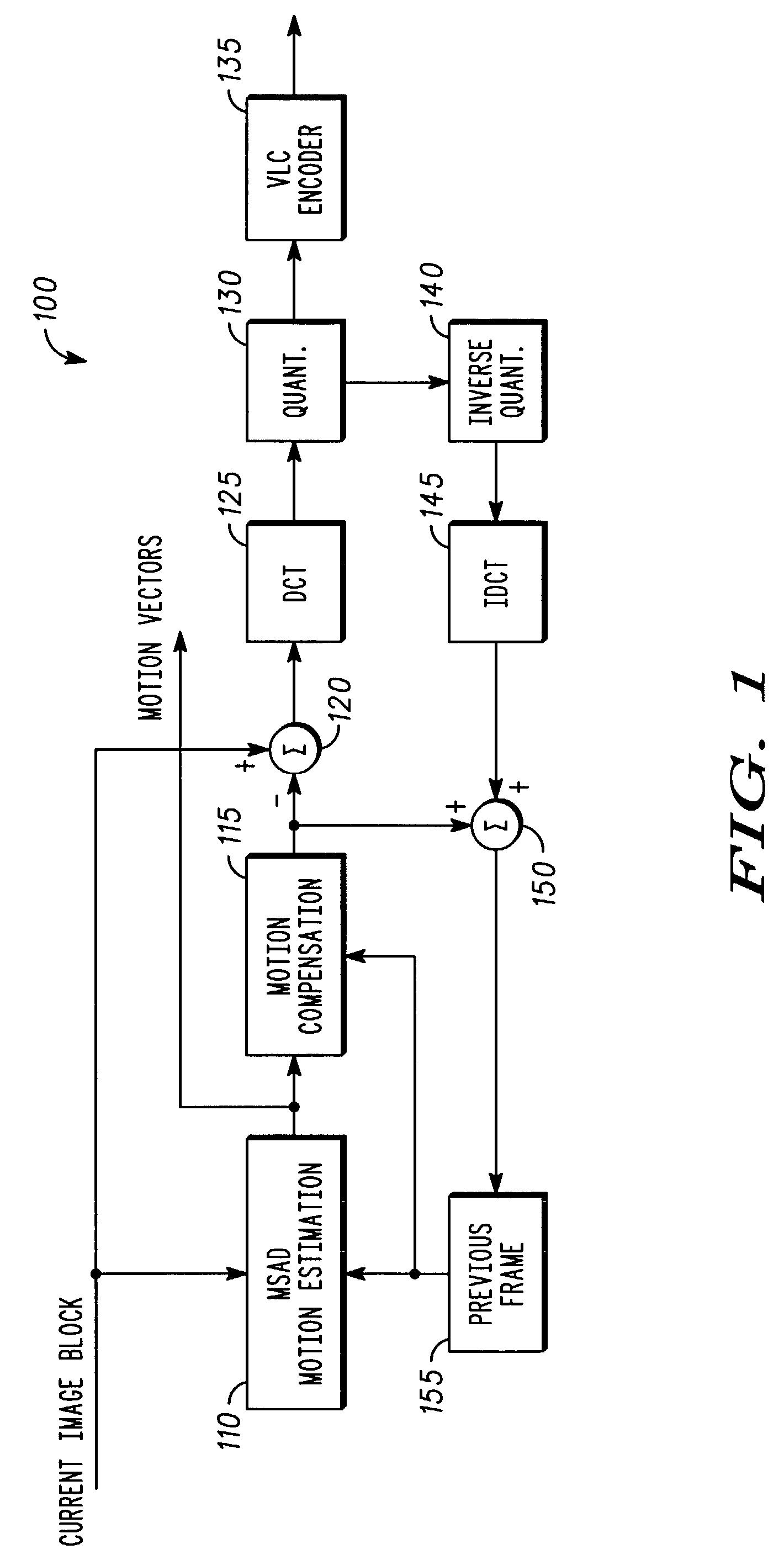
[0013]A method and apparatus for determining the quality of a block match for a candidate motion vector in a video encoder system using motion vectors representing the difference in coordinates of a macroblock of data in a current frame of video data and coordinates of a related macroblock of data in a reference frame of video data. The method can include defining a search pattern, searching a region based on the search pattern for a candidate motion vector for evaluation, calculating a difference metric, calculating a bias based on the difference between a predictor motion vector and a candidate motion vector, determining a modified difference metric by adding the difference metric to the bias, and defining a final motion vector based on the modified difference metric.

Problems solved by technology

Unfortunately, FSME becomes prohibitive as the search window is increased.
Another problem exists for FSME in that use of the SAD metric requires an excessive number of bits needed to encode motion vectors which results in compression inefficiency.
All off these algorithms suffer from either offering poorer quality or from not offering enough reduction in computational complexity.
Unfortunately, this approach does not give consistently good results over a wide range of video sequences.
Unfortunately, this approach gives a very similar result when compared to the zonal approach.

Method used


Image

  • Method and apparatus for determining block match quality
  • Method and apparatus for determining block match quality
  • Method and apparatus for determining block match quality

Examples


Embodiment Construction

[0021]The present invention gives an improved performance over a wide range of video sequences. There are several improvements and new algorithmic innovations that result in better quality. In fact, when averaged over several video sequences, the present invention can assist in improving the performance of the traditional full search algorithm in terms of achieved video compression efficiency.

[0022]All the methods used in prior art focus on optimizing the block match, while, among other benefits, the present invention can explicitly take into account the number of bits needed to encode the video sequence. The present invention can also take advantage of the nature of motion encountered in real life video capture.

[0023]Presently, with the wireless market taking off, there will be more requirements to enable video encoding technology on hand-held devices. Most of these devices do not have the processing capability to perform the intense computations of motion estimation. Thus, the hig...


PUM


Abstract

A method and apparatus for determining the quality of a block match for a candidate motion vector in a video encoder system using motion vectors representing the difference in coordinates of a macroblock of data in a current frame of video data and coordinates of a related macroblock of data in a reference frame of video data. The method can include defining a search pattern, searching a region based on the search pattern for a candidate motion vector for evaluation, calculating a difference metric, calculating a bias based on the difference between a predictor motion vector and a candidate motion vector, determining a modified difference metric by adding the difference metric to the bias, and defining a final motion vector based on the modified difference metric.

Description

BACKGROUND OF THE INVENTION[0001]1. Field of the Invention[0002]This invention relates to the field of motion estimation, and in particular to block-based motion estimation as applied to video image compression.[0003]2. Description of Related Art[0004]Presently, motion estimation is a key component of many video compression techniques. The purpose of motion estimation is to reduce temporal redundancy between frames of a video sequence. A motion estimation algorithm predicts image data for an image frame using one or more previously coded image frames or future frames. A difference image is computed by taking the arithmetic difference between the original pixel data and the corresponding predicted pixel data. A difference image with large variations indicates little or no temporal redundancy between the image frames. Whereas, a difference image with small variations indicates a high degree of temporal redundancy between the image frames. The difference image represents a reduced temp...

Claims


Application Information

Patent Timeline
Patent Type & Authority Patents(United States)
IPC IPC(8): H04N7/12H04N5/00G06T7/20H04N7/26
CPCG06T7/2026H04N19/567H04N19/51H04N19/176G06T2207/10016G06T7/238
Inventor SUBRAMANIYAN, RAGHAVANGANDHI, BHAVAN
Owner GOOGLE TECH HLDG LLC
Learn More