Determining fencing blade quality using dynamic magnetic field measurements

a dynamic magnetic field and measurement technology, applied in the field of fencing blade quality determination, can solve the problems of high hardness, more easily corroded, deformed, shattered, etc., and achieve the effect of reducing the risk of injury, and reducing the safety of fencers

Active Publication Date: 2019-09-12
CHEN LUCAS
View PDF0 Cites 0 Cited by
  • Summary
  • Abstract
  • Description
  • Claims
  • Application Information

AI Technical Summary

Benefits of technology

[0009]An apparatus may determine the quality of a fencing blade. The apparatus may include an electrical current source; a fencing blade to be tested for quality; two electrical cables, each connected between the electrical current source and the fencing blade so as to cause current from the current source to travel through at least a portion of the fencing blade; and a magnetic field sensor in sufficient proximity to the fencing blade so as to enable the magnetic field sensor to detect a magnetic field generated by the fencing blade when the current passes through the fencing blade.

Problems solved by technology

A blade that has a lower hardness may be more easily corroded, deformed, and / or shattered, thus creating a safety danger.
Despite the importance of blade quality, it can be difficult for a fencer to differentiate between blades of high and low quality, as many blades have similar appearance and feel.
But any brand, however famous or expensive, can be made of good or inferior batches of metal during production.
In addition, the prevalence of counterfeits can leave any fencer vulnerable to injury from a broken blade.
Traditional methods of testing metal, such an appearance testing (color and machine marks), spark testing (grinding metal to generate sparks and to assess steel quality based on sparks color and quality), and the Rockwell or Brinell or Vickers tests (estimate metal hardness by measuring the depth or width of indentation from a pounding machine), can be subjective and inaccurate.
But these tests can require expensive and cumbersome equipment.

Method used


Image

  • Determining fencing blade quality using dynamic magnetic field measurements
  • Determining fencing blade quality using dynamic magnetic field measurements
  • Determining fencing blade quality using dynamic magnetic field measurements

Examples


Embodiment Construction

[0034]Illustrative embodiments are now described. Other embodiments may be used in addition or instead. Details that may be apparent or unnecessary may be omitted to save space or for a more effective presentation. Some embodiments may be practiced with additional components or steps and / or without all of the components or steps that are described.

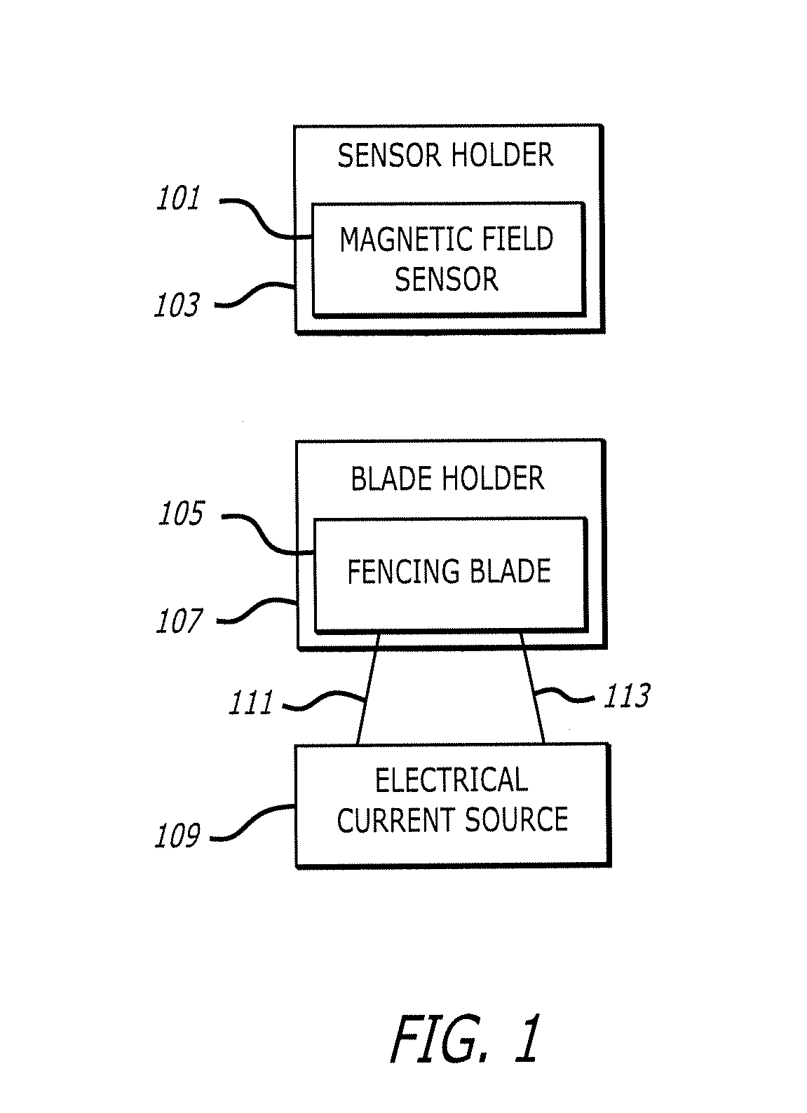
[0035]FIG. 1 illustrates an example of an apparatus for determining the quality of fencing blades. As illustrated in FIG. 1, the apparatus may include a magnetic field sensor 101 securely held in position by a sensor holder 103, a fencing blade 105 securely held in position by a blade holder 107, and an electrical current source 109 connected to the fencing blade by electrical cables 109 and 111.

[0036]The magnetic field sensor 101 may be of any type. The magnetic field sensor 101 may be capable of measuring the magnitude and / or direction of a magnetic field in which the sensor is present. The magnetic field sensor 101 may include a magneto...


PUM

PropertyMeasurementUnit
lengthaaaaaaaaaa
magnetic fieldaaaaaaaaaa
electrical currentaaaaaaaaaa

Abstract

An apparatus may determine the quality of a fencing blade. The apparatus may include an electrical current source; a fencing blade to be tested for quality; two electrical cables, each connected between the electrical current source and the fencing blade so as to cause current from the current source to travel through at least a portion of the fencing blade; and a magnetic field sensor in sufficient proximity to the fencing blade so as to enable the magnetic field sensor to detect a magnetic field generated by the fencing blade when the current passes through the fencing blade.

Description

BACKGROUNDTechnical Field[0001]This disclosure relates to fencing weapons, magnetic fields, and fencing weapon quality.Description of Related Art[0002]The sport of fencing is as old as the history of warfare, as soldiers practiced and drilled sword fighting in their extra time. Fencing became an official Olympic sport in 1896, with the Athens Olympic Games. The sport is now divided into three weapon classes: foil, epee, and saber. As the rules and scoring are different, each fencing category has evolved differently. Nevertheless, all modern-day fencing weapons are made with similar material, predominantly carbon tempered steel alloys.[0003]This steel may be made primarily of raw iron, which may contain varying amount of carbon (e.g., 0.25-2%), sulfur (e.g., <0.05%), phosphorus (e.g., <0.04%), and silicon (e.g., 0.3-0.5%). The iron may be mixed with different elements, such as manganese, nickel, chromium, molybdenum, vanadium, silicon, boron, aluminum, cobalt, copper, cerium, n...

Claims


Application Information

Patent Timeline
Patent Type & Authority Applications(United States)
IPC IPC(8): A63B69/02A63B71/04G01N27/80F41B13/02
CPCA63B69/02A63B71/04F41B13/02G01N27/80
Inventor CHEN, LUCAS
Owner CHEN LUCAS
Why Eureka
Try Eureka