Systems and methods for communicating with implantable devices

a technology of implantable devices and communication methods, applied in the field of systems and methods for controlling and/or energizing devices, can solve the problems of not being able to communicate effectively with implants located deep within the body, voltage that is too low to provide a reliable switching mechanism, and exposing the patient to false positives, so as to minimize the risk of accidental activation or deactivation of implants

Inactive Publication Date: 2006-04-04
REMON MEDICAL TECH
View PDF24 Cites 523 Cited by
  • Summary
  • Abstract
  • Description
  • Claims
  • Application Information

AI Technical Summary

Benefits of technology

[0011]In a preferred embodiment, the external controller's processor controls the first acoustic transducer to transmit a first acoustic signal/or and a second acoustic signal. The switch of the implant may be closed when the first acoustic signal is received by the second acoustic transducer, while the switch may be opened when the second acoustic signal is received by the second acoustic transducer. In addition or alternatively, the first acoustic transducer may transmit first and second acoustic signals separated by a delay. The switch may be closed and/or opened only when the second acoustic transducer receives the first and second acoustic signals separated by a predetermined delay, thereby minimizing the risk of acciden

Problems solved by technology

RF energy, however, may only penetrate a few millimeters into a body, because of the body's dielectric nature, and therefore may not be able to communicate effectively with an implant that is located deep within the body.
In addition, although an RF transmitter may be able to induce a current within an implant, the implant's receiving antenna, generally a low impedance coil, may generate a voltage that i

Method used


Image

  • Systems and methods for communicating with implantable devices
  • Systems and methods for communicating with implantable devices
  • Systems and methods for communicating with implantable devices

Examples


Embodiment Construction

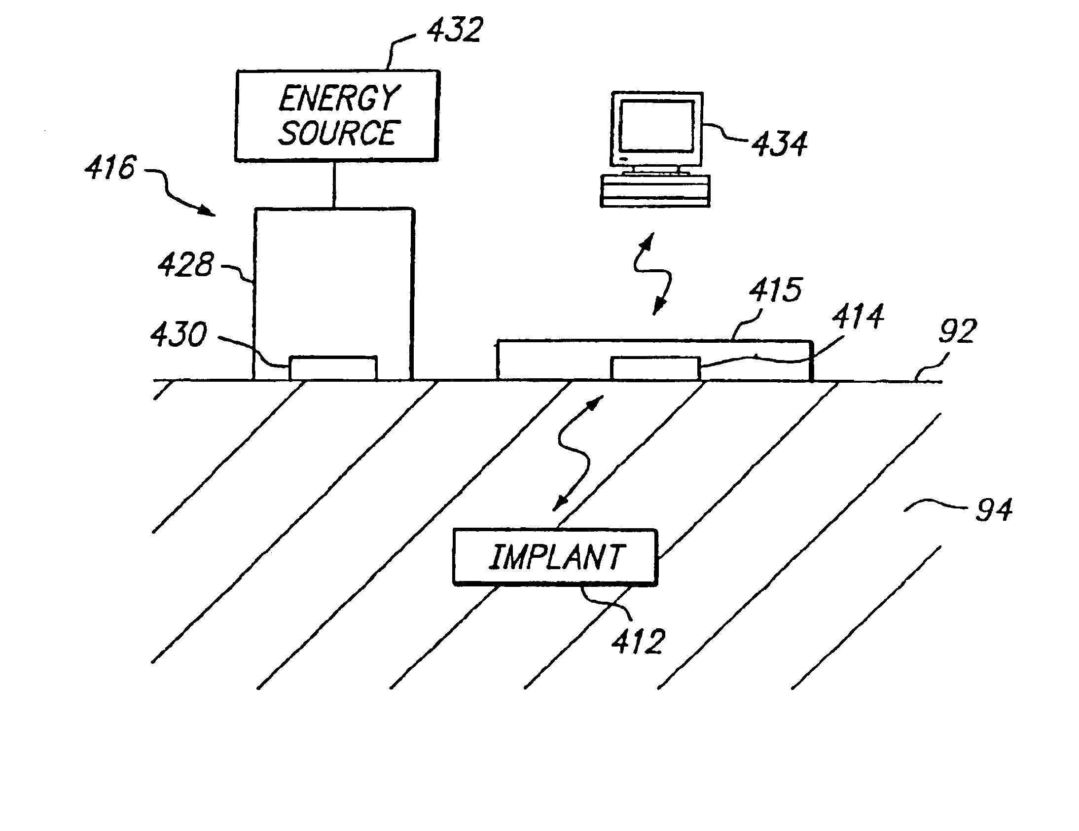
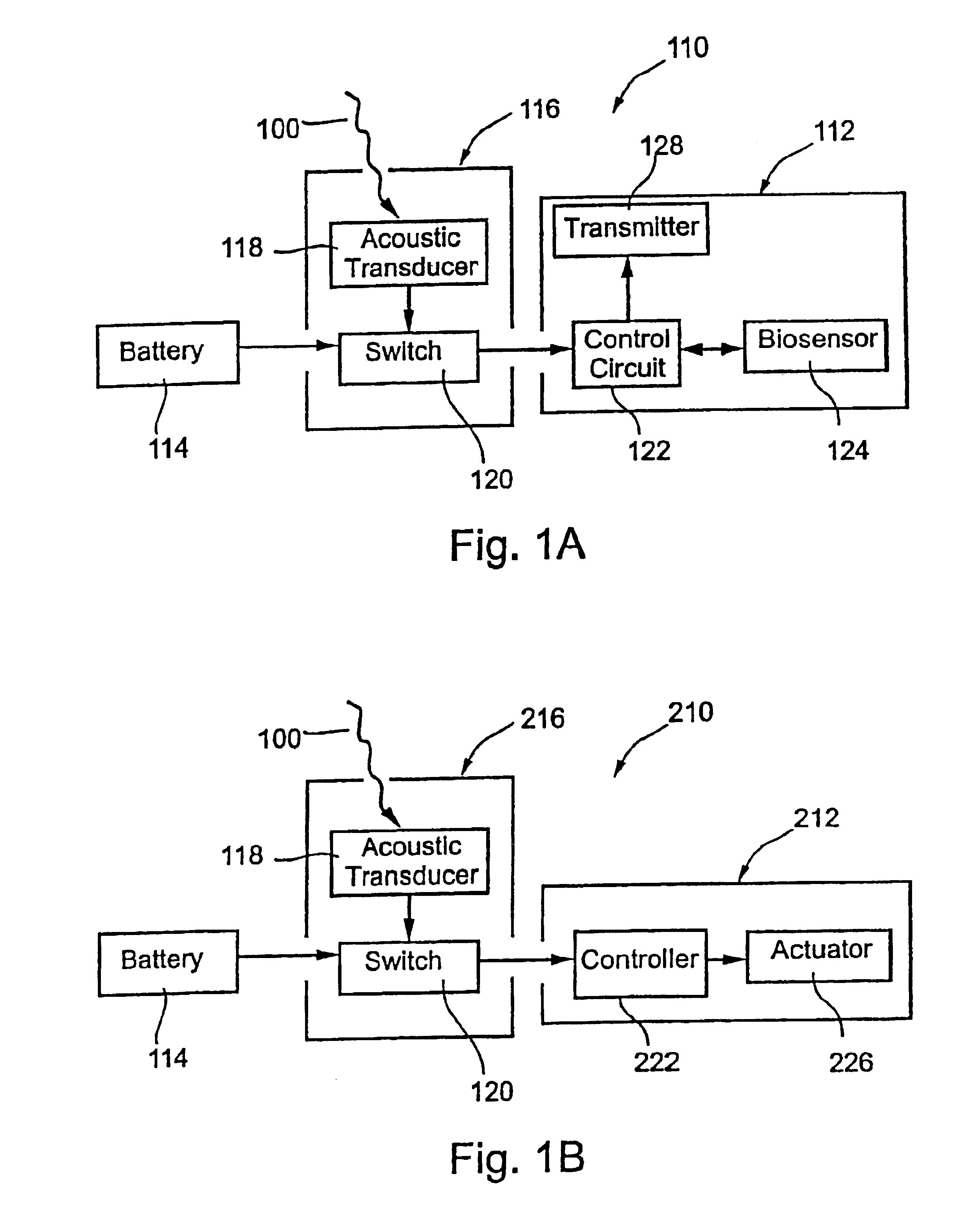
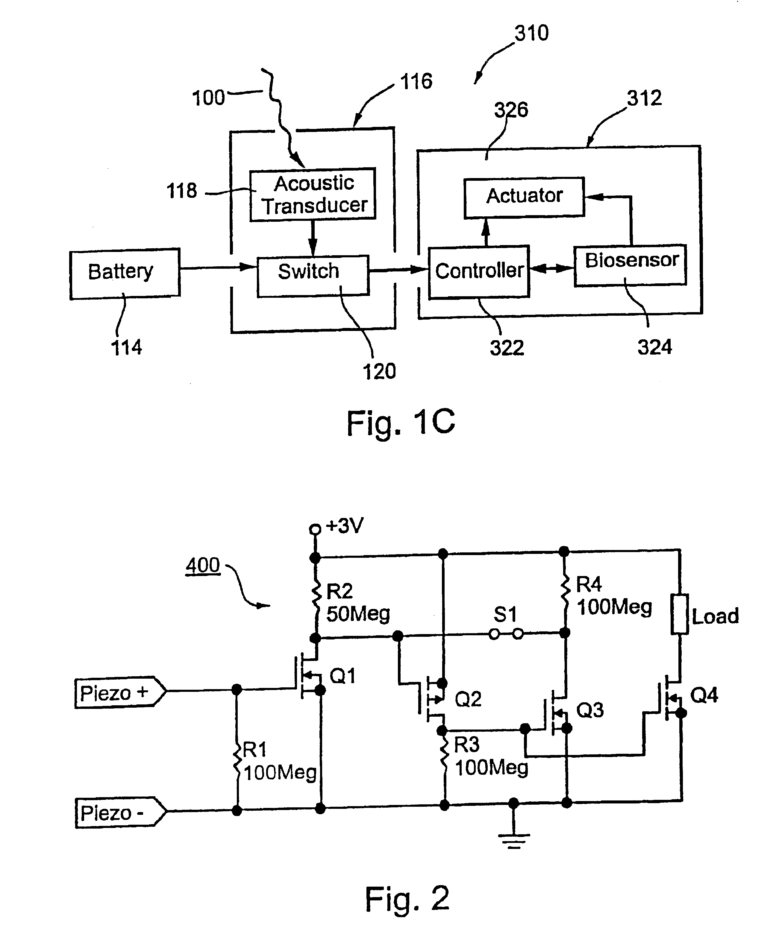
[0024]Turning to the drawings, FIGS. 1A-1C schematically show several exemplary embodiments of an implant 110, 210, 310, in accordance with the present invention. Generally, the implant 110, 210, 310 includes an electrical circuit 112, 212, 312 configured for performing one or more functions or commands when the implant 110, 210, 310 is activated, as described furtherbelow. In addition, the implant 110, 210, 310 includes an energy storage device 114 and optionally may include a switch 116 coupled to the electrical circuit 112, 212, 312 and the energy storage device 114. The switch 116 may be activated upon acoustic excitation 100 from an external acoustic energy source (not shown) to allow current flow from the energy storage device 114 to the electrical circuit 112, 212, 312.

[0025]In a preferred embodiment, the switch 116 includes an acoustic transducer 118, such as that disclosed in PCT Publication No. WO 99 / 34,453, published Jul. 8, 1999, or in U.S. application Ser. No. 09 / 888,27...


PUM


Abstract

Systems and methods for communicating with an implant within a patient's body using acoustic telemetry includes an external communications device attachable to the patient's skin. The device includes an acoustic transducer for transmitting acoustic signals into the patient's body and/or for receiving acoustic signals from the implant. The device includes a battery for providing electrical energy to operate the device, a processor for extracting data from acoustic signals received from the implant, and memory for storing the data. The device may include an interface for communicating with a recorder or computer, e.g., to transfer data from the implant and/or to receive instructions for controlling the implant. The device is secured to the patient's skin for controlling, monitoring, or otherwise communicating with the implant, while allowing the patient to remain mobile.

Description

[0001]This application is a Continuation-in-Part of application Ser. No. 09 / 690,615, filed Oct. 16, 2000 now U.S. Pat. No. 6,628,989 granted Sep. 30, 2003 and entitled “Acoustic Switch and Apparatus and Methods for Using Acoustic Switches Within a Body,” the disclosure of which is expressly incorporated herein by reference.FIELD OF THE INVENTION[0002]The present invention relates generally to systems and methods for measuring physiological conditions and / or performing therapeutic functions within a patient's body, particularly to systems and methods for controlling and / or energizing devices that may be implanted within a body, and more particularly to implants that may be energized, activated, controlled, and / or otherwise communicate via acoustic energy.BACKGROUND OF THE INVENTION[0003]Devices are known that may be implanted within a patient's body for monitoring one or more physiological conditions and / or to provide therapeutic functions. For example, sensors or transducers may be ...

Claims


Application Information

Patent Timeline
IPC IPC(8): A61N1/18A61B5/00A61B5/0215A61B5/07A61B5/103A61B8/00A61M37/00A61N1/08A61N1/34A61N1/36A61N1/372A61N1/378
CPCA61B5/00A61B5/02A61B5/0215A61B5/076A61B5/1112A61B5/14539A61B5/4839A61B8/56A61N1/08A61N1/37217A61N1/3787A61B5/0031Y10S128/903A61B8/4281A61B8/4472A61B2560/0209A61B2560/0214A61B2560/0219A61B2560/0242A61B2560/0257A61B2560/0412A61B2562/028A61N1/37235A61N1/37252
Inventor PENNER, AVLDORON, EYAL
Owner REMON MEDICAL TECH
Why Eureka
Try Eureka