Methods and apparatus for electronically modeling aircraft engine harnesses

a technology of aircraft engine and harness, applied in the field of aircraft engine harnesses, can solve problems such as inaccurate results, and achieve the effect of cost-effective and reliable, and facilitate the accurate unfolding of three-dimensionally defined harnesses

Inactive Publication Date: 2006-04-04
GENERAL ELECTRIC CO
View PDF15 Cites 7 Cited by
  • Summary
  • Abstract
  • Description
  • Claims
  • Application Information

AI Technical Summary

Benefits of technology

[0006]In an exemplary embodiment, a modeling system converts a three-dimensionally defined aircraft engine harness into a two-dimensional electronic model. Specifically, the modeling system electronically unfolds the three-dimensionally defined harness to create a plurality of two-dimensional stick format drawings that are viewable along a plurality of orientations. Furthermore, a processor executing the modeling system determines a plurality of design parameters for the ha

Problems solved by technology

Because of the complexity of the aircraft engines, the harnesses are often complex, and the process of determining an unfolded st

Method used


Image

  • Methods and apparatus for electronically modeling aircraft engine harnesses
  • Methods and apparatus for electronically modeling aircraft engine harnesses
  • Methods and apparatus for electronically modeling aircraft engine harnesses

Examples


Embodiment Construction

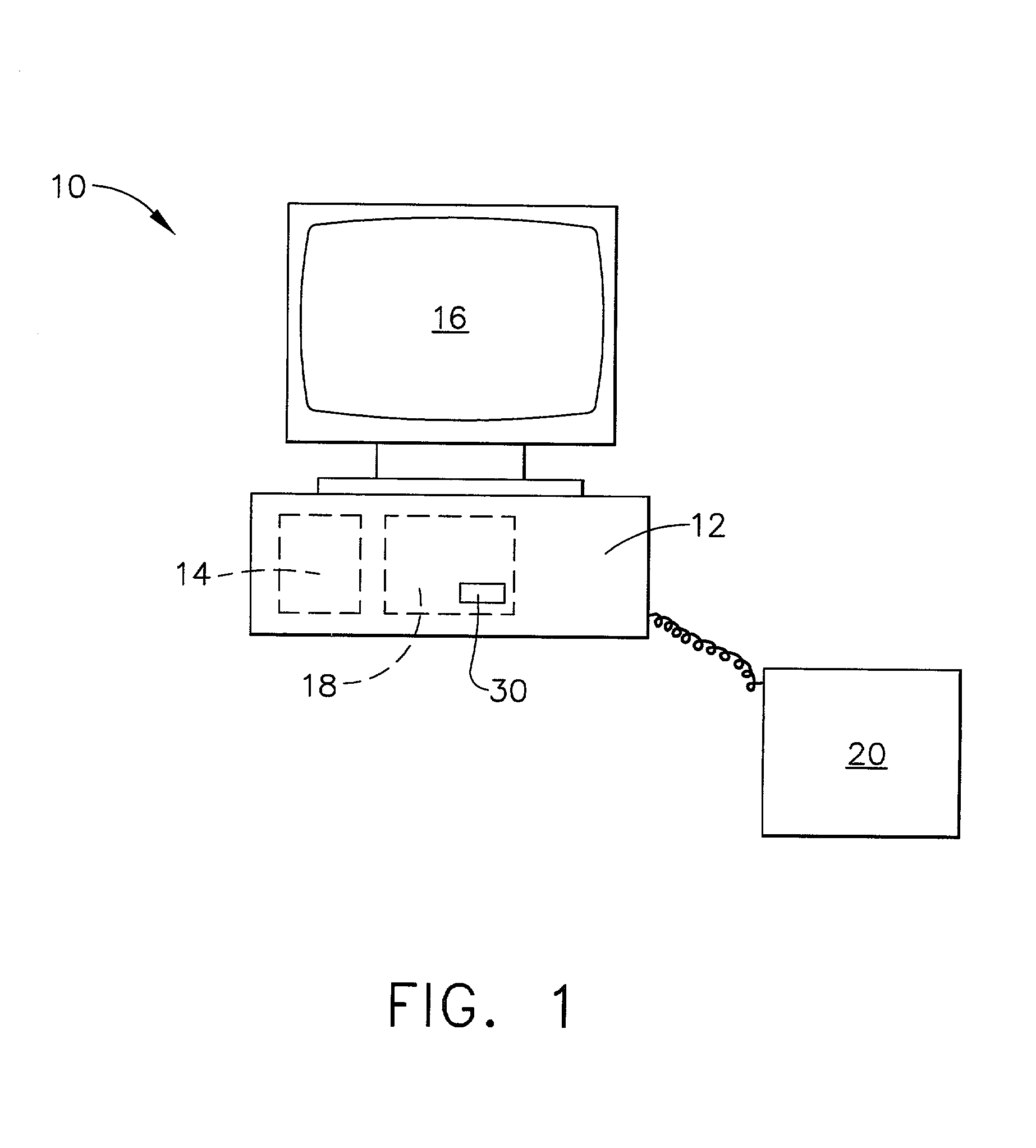
[0014]FIG. 1 is a block diagram of a processing system 10 according to one embodiment of the present invention. Processing system 10 includes a central processing unit (CPU) 12, a random access memory (RAM) 14, an output device 16, for example a monitor, a mass storage device 18, and an input device 20, for example a keyboard. Processing system 10 may be a single user system, for example, a microcomputer, or a multi-user system including a server (not shown) and a plurality of devices (not shown) connected to the server. In one embodiment, processing system 10 is accessible via the Internet through many interfaces including through a network, such as a local area network (LAN) or a wide area network (WAN), through dial-in-connections, cable modems and special high-speed ISDN lines. Additionally, system 10 may include multiple input devices 20, i.e., a keyboard, a mouse, or various automated data input devices, i.e., an optical scanner (not shown). A modeling system program 30 is sto...


PUM

PropertyMeasurementUnit
Lengthaaaaaaaaaa
Angleaaaaaaaaaa

Abstract

A modeling system that converts a three-dimensionally defined aircraft engine harness in a two-dimensional electronic model, a process known as unfolding, is described. The modeling system electronically unfolds the three-dimensionally defined harness to create a two-dimensional representation, while simultaneously determining a plurality of design parameters. The drawing and the design parameters are displayed in a format that may be used for inspection purposes and manufacturing purposes. More specifically, the modeling system determines branch angles, wire lengths, and a plurality of angles of the three-dimensionally defined harness.

Description

[0001]This application claims priority to the provisional patent application filed Oct. 19, 2000, Ser. No. 60 / 241,560.BACKGROUND OF THE INVENTION[0002]This invention relates generally to aircraft engine harnesses and, more particularly, to modeling systems used to model aircraft engine harnesses.[0003]Aircraft engines typically include a plurality of wiring harnesses used to electrically couple a plurality of engine components. Each harness includes a plurality of connectors electrically coupled with a plurality of wire cables. The harnesses typically include a plurality of wire cable branches extending in various angles and directions from a central wire cable.[0004]During an initial assembly of an aircraft engine, an engine mock-up is utilized to determine how each wiring harness should be routed across the engine. More specifically, rope is often routed across the engine to simulate the wiring harness and to produce a template of each wiring harness.[0005]Once the desired assembl...

Claims


Application Information

Patent Timeline
IPC IPC(8): G06F17/50B64F5/00
CPCG06F17/5095Y10T29/49201G06F2217/36G06F30/15G06F2113/16
Inventor BARROW, PATRICKMEYERS, DUSTIN LEEHOELLE, JAMES STEPHENJUNGEBERG, KENNETH ALVIN
Owner GENERAL ELECTRIC CO
Why Eureka
Try Eureka