Transmission format detection method
a technology of transmission format and detection method, applied in the field of communication system, can solve the problems of large operation amount, error in transmission line, error correction decoding, etc., and achieve the effect of improving the efficiency of error detection
- Summary
- Abstract
- Description
- Claims
- Application Information
AI Technical Summary
Benefits of technology
Problems solved by technology
Method used
Image

Examples
first embodiment
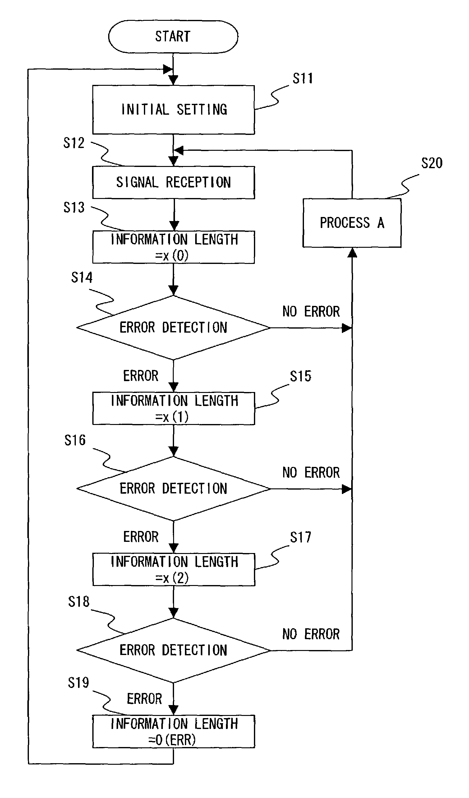
[0095]Next, specific embodiments are described. FIG. 8 is a flowchart showing the BTFD algorithm of the present invention. This embodiment is based on the algorithm shown in FIG. 3. Among the step numbers used in FIG. 8, the same numbers as those used in FIG. 3 represent the same processes.
[0096]In the first embodiment, the information length of a received radio frame is set as the first predicted value in a process for detecting the information length of the next radio frame. In other words, on receipt of a radio frame, first, the information length detection process is performed assuming that the information length of a current radio frame is the same as the information length of the previous radio frame. Then, if the trial fails, another predicted value is used.
[0097]Specifically, according to the algorithm of the first embodiment, steps S42 and 43 are executed as step S20 (process A) shown in FIG. 3. Step S41 is provided in order to execute steps S42 and 43. Step S41 is executed...
case 1
[0105] Consecutively receiving frames storing 100 bits of information, after consecutively receiving a prescribed number of frames storing 50 bits of information.
[0106]In this case, while consecutively receiving frames storing 50 bits of information, no error is detected in the error detection process using the first predicted value (50 bits). Specifically, “no error” is detected in step S14, and neither step S16 nor S18 is executed. Therefore, the memory areas x(0) through x(2) are not updated, and the respective states shown in FIG. 9A are maintained.
[0107]Then, when a frame storing 100 bits of information is received, no error is detected in the error detection process using the second predicted value (100 bits). Specifically, “no error” is detected in step S16, and step S42 is executed. In step 42, as described above, currently used second predicted value is written in the memory area x(0), and currently used first predicted value is written in the memory area(1). As a result, t...
case 2
[0109] Consecutively receiving frames storing 200 bits of information, after consecutively receiving a prescribed number of frames storing 50 bits of information.
[0110]In this case, the operations performed while consecutively receiving frames storing 50 bits of information is the same as the operations in case 1. On receipt of a frame storing 200 bits of information, no error is detected in the error detection process using the third predicted value (200 bits). Specifically, “no error” is detected in step S18, and step S43 is executed. In step S43, as described above, currently used third predicted value is written in the memory area x(0), and currently used first predicted value is written in the memory area x(2). As a result, the memory areas x(0) through x(2) hold respective states shown in FIG. 9C.
[0111]Then, while consecutively receiving frames storing 200 bits of information, no error is detected in the error detection process using the first predicted value (200 bits). Speci...
PUM
 Abstract
Description
Claims
Application Information
 - R&D
- Intellectual Property
- Life Sciences
- Materials
- Tech Scout
- Unparalleled Data Quality
- Higher Quality Content
- 60% Fewer Hallucinations
Browse by: Latest US Patents, China's latest patents, Technical Efficacy Thesaurus, Application Domain, Technology Topic, Popular Technical Reports.
© 2025 PatSnap. All rights reserved.Legal|Privacy policy|Modern Slavery Act Transparency Statement|Sitemap|About US| Contact US: help@patsnap.com