Method and apparatus for controlling dispersion of molten metal in a mold cavity

Inactive Publication Date: 2006-04-11
GM GLOBAL TECH OPERATIONS LLC
View PDF2 Cites 10 Cited by
  • Summary
  • Abstract
  • Description
  • Claims
  • Application Information

AI Technical Summary

Benefits of technology

[0009]Consistent and consonant with the present invention, a method and apparatus for controlling dispersion of molten metal in a mold cavity for a lost foam casting process wherein the filling of regions of the mold cavity which do not l

Problems solved by technology

The casting rate or rate at which the molten metal enters the mold cavity is limited by the rate the advancing molten metal front can displace the pattern from the cavity.
Casting engineers are often challenged with a part config

Method used


Image

  • Method and apparatus for controlling dispersion of molten metal in a mold cavity
  • Method and apparatus for controlling dispersion of molten metal in a mold cavity
  • Method and apparatus for controlling dispersion of molten metal in a mold cavity

Examples


Embodiment Construction

[0020]The following detailed description and appended drawings describe and illustrate various exemplary embodiments of the invention. The description and drawings serve to enable one skilled in the art to make and use the invention, and are not intended to limit the scope of the invention in any manner. In respect of the process disclosed and the flow diagrams illustrated, the steps presented are exemplary in nature, and thus, the order of the steps is not necessary or critical.

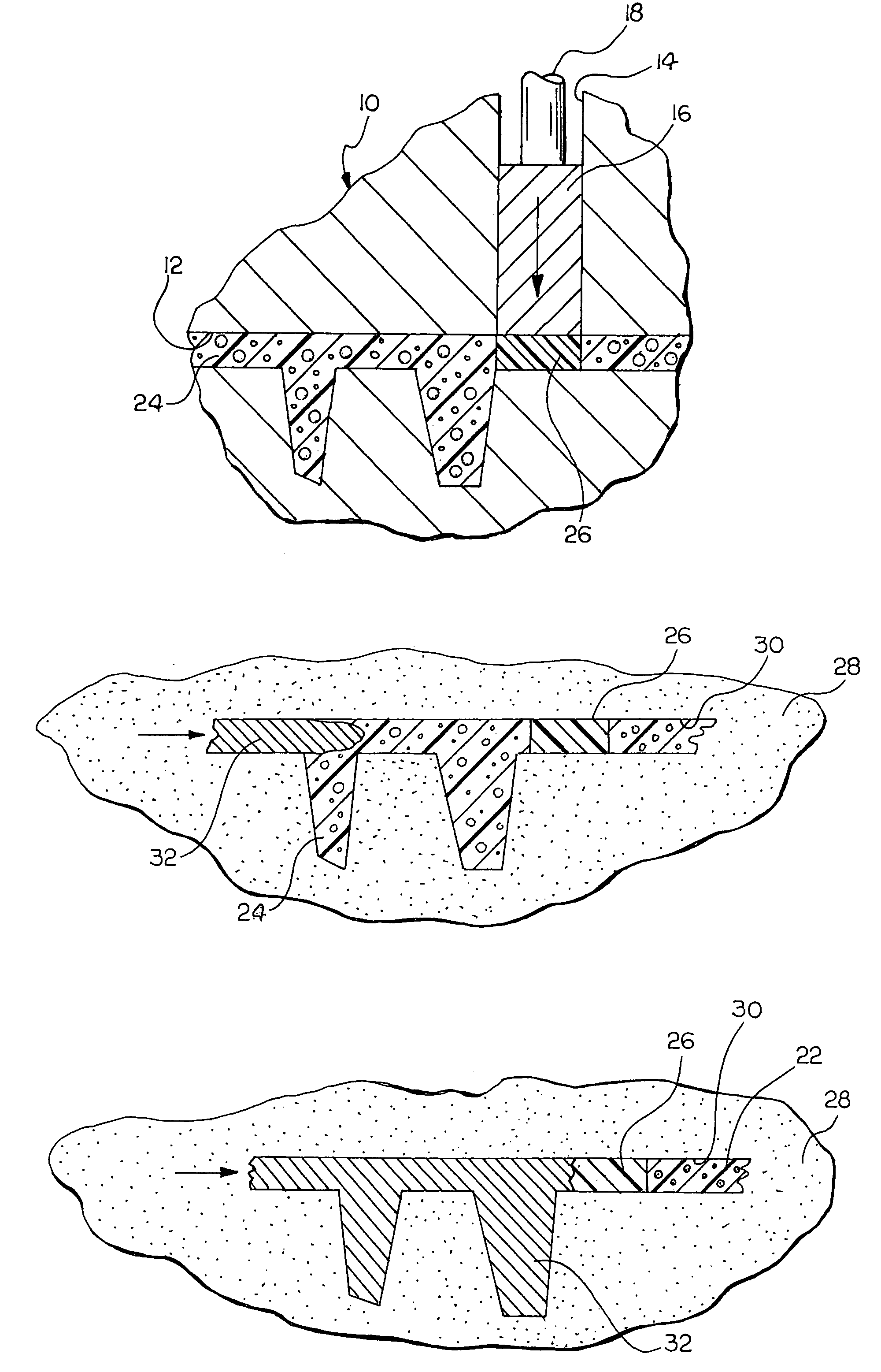
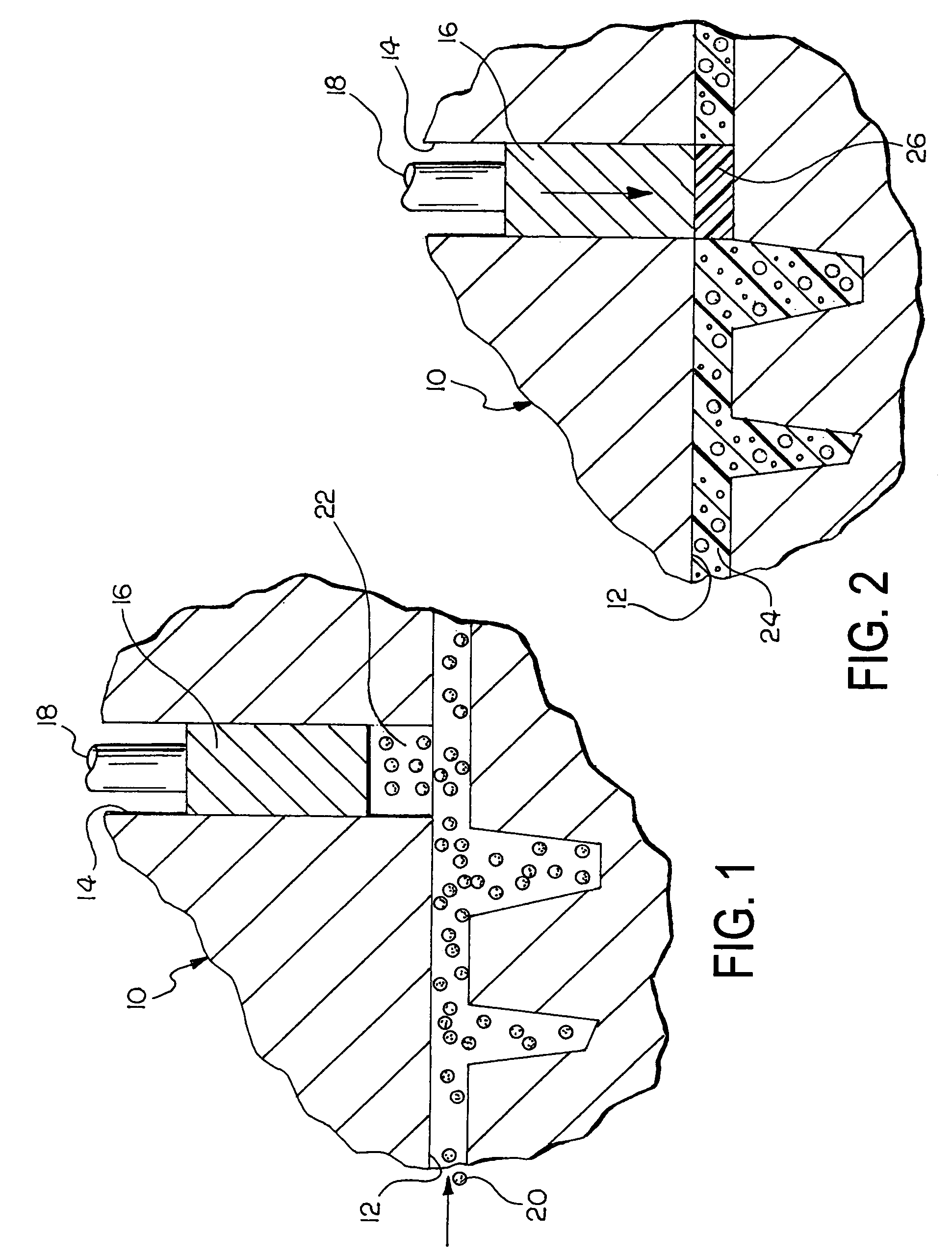
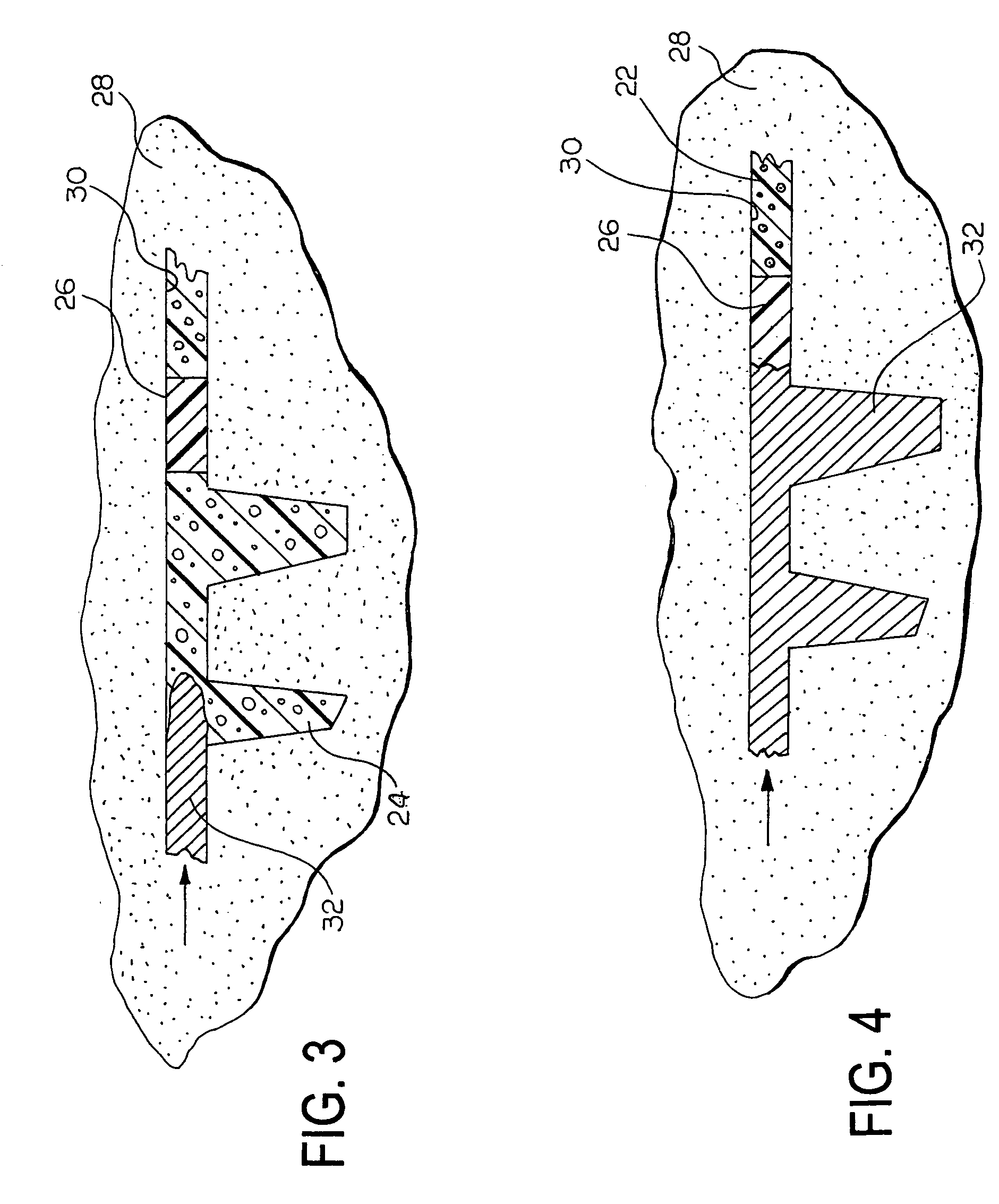
[0021]FIG. 1 depicts a lost foam pattern die 10 according to an embodiment of the invention. The die 10 includes a pattern forming cavity 12 formed therein. The cavity 12 has a shape substantially the same as a desired cast part (not shown). A cylinder 14 is formed in the die 10 and is in communication with the cavity 12. Cylinder as used herein is meant to mean a through-hole, cavity or other chamber adapted to have a sliding member disposed therein.

[0022]A squeeze pin 16 is slidably disposed in the cylinde...


PUM

PropertyMeasurementUnit
Pressureaaaaaaaaaa
Dispersion potentialaaaaaaaaaa
Densityaaaaaaaaaa

Abstract

A method and apparatus for controlling the dispersion of molten metal in a mold cavity is disclosed, the control facilitated by a localized densification of foam in a lost foam casting operation for producing metal castings, wherein the filling of regions of the mold cavity which do not lend themselves to castability is maximized, an amount of backfill and casting defects are minimized, and a flow pattern of molten metal and material properties of the resulting casting are optimized.

Description

FIELD OF THE INVENTION[0001]The invention relates to lost foam casting and more particularly to a method and apparatus for controlling dispersion of molten metal in a mold cavity in a lost foam casting process for producing metal castings, wherein the control is facilitated by a localized densification of the foam.BACKGROUND OF THE INVENTION[0002]A so-called “lost-foam” casting process is a well-known technique for producing metal castings. A fugitive, pyrolizable, polymeric, foam pattern (including casting, gating, runners, and sprue) is covered with a thin (typically in the range of 0.25–0.5 mm), gas-permeable refractory coating / skin such as mica, silica, alumina, or alumina-silicate, for example. The pattern is embedded in compacted, unbonded sand to form a mold cavity within the sand. Molten metal is then introduced into the mold cavity to melt, pyrolyze, and displace the pattern with molten metal.[0003]Gaseous and liquid decomposition / pyrolysis products escape through the gas-p...

Claims


Application Information

Patent Timeline
IPC IPC(8): B22C9/04
CPCB22C7/023
Inventor WARD, GARY C.PRIEM, BARRY L.
Owner GM GLOBAL TECH OPERATIONS LLC
Why Eureka
Try Eureka