
Optical apparatus, shutter device, and camera

Active Publication Date: 2006-04-11
OM DIGITAL SOLUTIONS CORP
View PDF9 Cites 7 Cited by
  • Summary
  • Abstract
  • Description
  • Claims
  • Application Information

AI Technical Summary

Benefits of technology

[0017]Another optical apparatus according to the present invention is characterized in that in an optical apparatus having a light-exclusion member capable of opening and shutting an opening for passing a photographing luminous flux therethrough, the structure is simple and an occupied area on a surface orthogonal to an optical axis is small.
[0018]Furthermore, a shutter device according to the present invention is characterized in that the rebound of shutter blades is suppressed, the structure is simplified, and a space for arrangement is small.

Problems solved by technology

Accordingly, a diaphragm opening must be relatively smaller; however, by the limit due to light-diffraction, the diaphragm opening cannot be reduced lower than a predetermined value so as to prevent the resolution to be deteriorated.
Also, in a shutter device for opening and shutting an exposure opening by operating conventional shutter blades, since the shutter blades are rapidly stopped when the blades reach the opened position or the shut position after the rotation (movement) at high speed, rebounding is liable to occur.

Method used


Image

  • Optical apparatus, shutter device, and camera
  • Optical apparatus, shutter device, and camera
  • Optical apparatus, shutter device, and camera

Examples


first embodiment

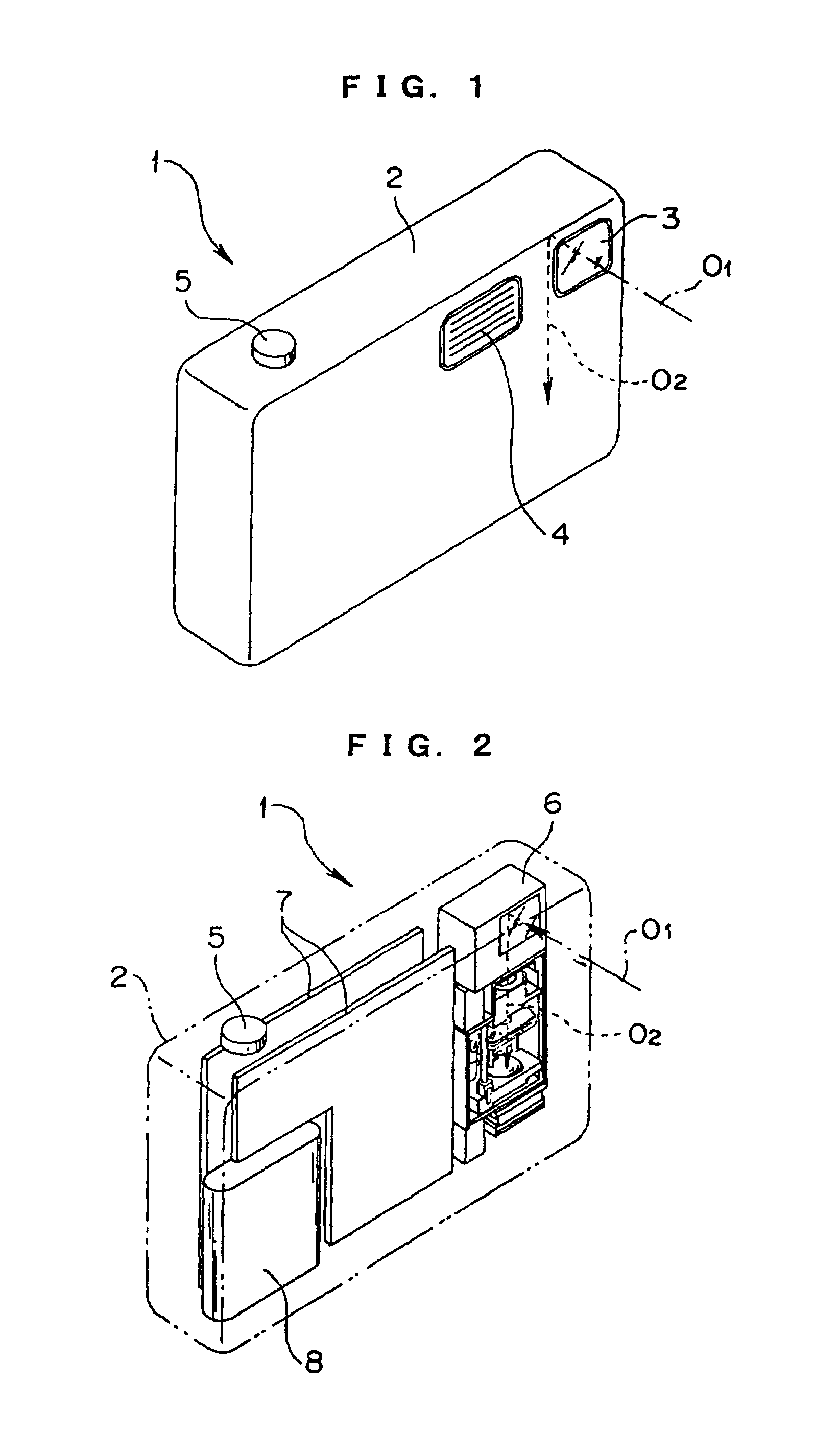
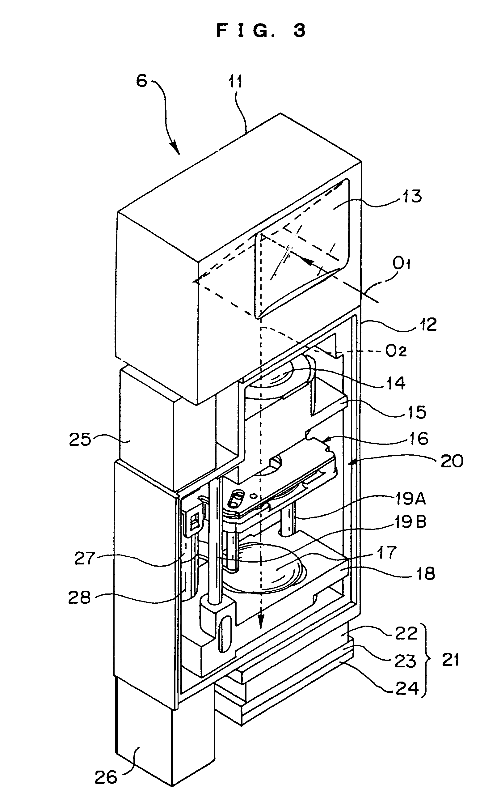
[0063]FIG. 1 is an exterior view of a camera (digital camera) having a shutter-filter unit of an optical apparatus applied thereto according to the present invention; FIG. 2 is a perspective view showing an internal arrangement of the camera; FIG. 3 is a perspective view of a lens-barrel unit housed in the camera; and FIG. 4 is a perspective view of a lens-device unit of the lens-barrel unit.

second embodiment

[0064]In the description below regarding arrangements, the left and right direction denotes the direction viewing a camera from an object; in the vertical direction, the upside is adjacent to an upper mirror frame 11, which will be described later, and as well as the incident side of an optical axis O2, which will be described later, and the downside is an image forming side, i.e., adjacent to the CCD unit 21. Furthermore, the rotational direction of each member of the optical apparatus is indicated by the rotational direction viewed from the above. These directional indications will be applied to the present invention, which will be described later.

[0065]A camera 1 according to the first embodiment of the present invention includes a camera external cover 2 that includes a taking window 3 for importing an object luminous flux in an optical axial direction O1 and a stroboscopic window 4 for emitting stroboscopic light, which are arranged on the front surface, and a release button 5 ...

third embodiment

[0152]FIG. 18 is an exploded perspective view of a shutter device according to the present invention; FIG. 19 is a plan view of the shutter device viewed from the incident side in the state that a case lid is removed from the shutter device showing primary and secondary blades in the shut state; FIG. 20 is a plan view of the shutter device also viewed from the incident side in the state that the case lid is removed from the shutter device showing only the primary blade in the opened state of the shutter; FIG. 21 is a sectional view at the line 21—21 of FIG. 18 showing the shut state of the shutter device; FIG. 22 is a sectional view at the line 22—22 of FIG. 18 showing the same shut state of the shutter device; and FIG. 23 is a sectional view at the line 23—23 of FIG. 18 schematically showing the dynamic displacement of the shutter blades when the device reaches the shutter shut position by enlarging the size in an optical axial direction O.

[0153]In the description below, symbol O d...


PUM


Abstract

A shutter / filter unit as an optical apparatus includes a shutter actuator, a filter actuator, a shutter drive ring, two shutter blades, and one ND filter, which are connected to a driving source body in series. The shutter blades are rotationally driven via the shutter drive ring so as to open and shut by the shutter actuator, and the ND filter is back and forth and rotationally driven by the filter actuator directly. The shutter blades and the ND filter are coaxially supported to a blade-support pin, and are rotationally driven independently. According to this apparatus, a conventional optical apparatus having a light-exclusion member and a light-attenuating member housed therein is further miniaturized so as to contribute miniaturization to an image-pickup apparatus, such as a camera, having the optical apparatus mounted thereon.

Description

CROSS REFERENCE TO RELATED APPLICATION(S)[0001]This application claims benefit of Japanese Applications No. 2002-334267 filed in Japan on Nov. 18, 2002, No. 2002-344217 filed in Japan on Nov. 27, 2002, and 2002-382363 filed in Japan on Dec. 27, 2002, the contents of which are incorporated by this reference.BACKGROUND OF THE INVENTION[0002]1. Field of the Invention[0003]The present invention relates to an optical apparatus having a light-attenuating device and a light-exclusion device assembled therein, and a structure of a camera having the optical apparatus further to a shutter device (optical device) having an exposure opening for passing photographing light therethrough, and a structure of a camera having the shutter device.[0004]2. Related Art Statement[0005]In a conventional optical system of an image-pickup apparatus such as a digital camera, there is a system having a light-attenuating filter (light-attenuating member) called an ND filter inserted therein. The reason for usin...

Claims


Application Information

Patent Timeline
IPC IPC(8): G03B9/08G03B9/00G03B9/14H04N5/225
CPCH04N5/2254G03B9/14H04N23/55
Inventor TAKANASHI, TATSUO
Owner OM DIGITAL SOLUTIONS CORP
Learn More