Compaction device for compacting moulded bodies from granular substances and method for using said device

a technology of granular substances and compacting moulded bodies, which is applied in the direction of dough shaping, baking, domestic objects, etc., can solve the problems of small uneven acceleration of vibrating tables, and achieve the effects of reducing mold wear, increasing the quality of the compaction process, and ensuring the consistency of the resul

Inactive Publication Date: 2006-04-11
GEDIB ING & INNOVATIONSBERATUNG
View PDF6 Cites 12 Cited by
  • Summary
  • Abstract
  • Description
  • Claims
  • Application Information

AI Technical Summary

Benefits of technology

[0015]It is the object of the invention to eliminate or reduce the disadvantages described above of the prior art, in which the compaction energy is introduced into the molded body predominantly by instances of impact of the vibrating table from below against the pallet. It is intended here for high impact frequencies to be used and for the compacting device to be able to operate with a compacting frequency that can be adjusted in a wide range (even during the compacting operation) up to highest frequencies of 75 Hz and higher, with a long service life of the components involved and with low energy expenditure. At the same time, it is also intended to use the means of the invention to improve the repeating accuracy of generating the compacting acceleration by the instances of impact on the pallet or on the underside of the molded body itself and the uniformity of the distribution of the compacting acceleration over the entire surface area of the pallet.
[0016]The invention uses, inter alia, the following principle: when conventionally generating the oscillating movement of the vibrating table by using springs which serve only for isolating oscillation and are therefore set soft, the accelerating forces which have to be applied to the oscillating masses are generated overwhelmingly by directed centrifugal forces of the unbalanced bodies. When generating the oscillating movements according to the invention, the accelerating forces are applied predominantly by spring forces and only to a smaller extent by the exciter forces of the exciter device, at least in that case in which they have to reach the highest values at the highest oscillating frequencies. This is achieved by using the effect of resonance amplification. In a further development of the invention, this effect is utilized even better by the fact that it is envisaged to allow not only the natural frequency lying in the range of the highest oscillating frequencies but also at least a second natural frequency of the mass-spring system to be produced in the range of the oscillating frequencies to be operationally covered. As shown in FIG. 6, this has the effect that the necessary exciter forces can be reduced still further, which, inter alia, also facilitates the use of AC linear motors commonly available on the market and likewise also the possibility of varying the compaction frequency over a wide frequency range during a compacting operation.
[0017]For storing the kinetic energy of the system mass taken along in the upward oscillating movement of the vibrating table, there can also be incorporated in the spring system spring elements whose spring force acts on the pallet from above, which also includes those spring forces which are concomitantly applied via the pressing plate. Insofar as this concerns those spring forces which are not passed via the pressing plate, as is the case for example with the springs 124 in FIG. 1, these contribute to allowing the oscillating stroke amplitude of the vibrating table or the mold also to be regulated according to given values when the compacting system is oscillating idly or during pre-compaction. The spring elements of the system spring storing the kinetic energy have to store a much higher amount of energy in comparison with the soft-set isolating springs in the case of the conventional compacting systems. Not only in the interests of their service life (risk of self-destruction by heat) but also for the purpose of avoiding unnecessary energy losses, the spring elements of the system spring are therefore preferably produced from steel or from a low-damping elastomer material or are embodied by an (intrinsically low-damping) liquid compressible medium.

Problems solved by technology

Possible closer arrangement of the unbalanced shafts, this feature leading to smaller unevennesses in the acceleration of the vibrating table as a result of incorrect rotational positions of the unbalanced bodies, because of the improved central application of the centrifugal forces.

Method used


Image

  • Compaction device for compacting moulded bodies from granular substances and method for using said device
  • Compaction device for compacting moulded bodies from granular substances and method for using said device
  • Compaction device for compacting moulded bodies from granular substances and method for using said device

Examples


Embodiment Construction

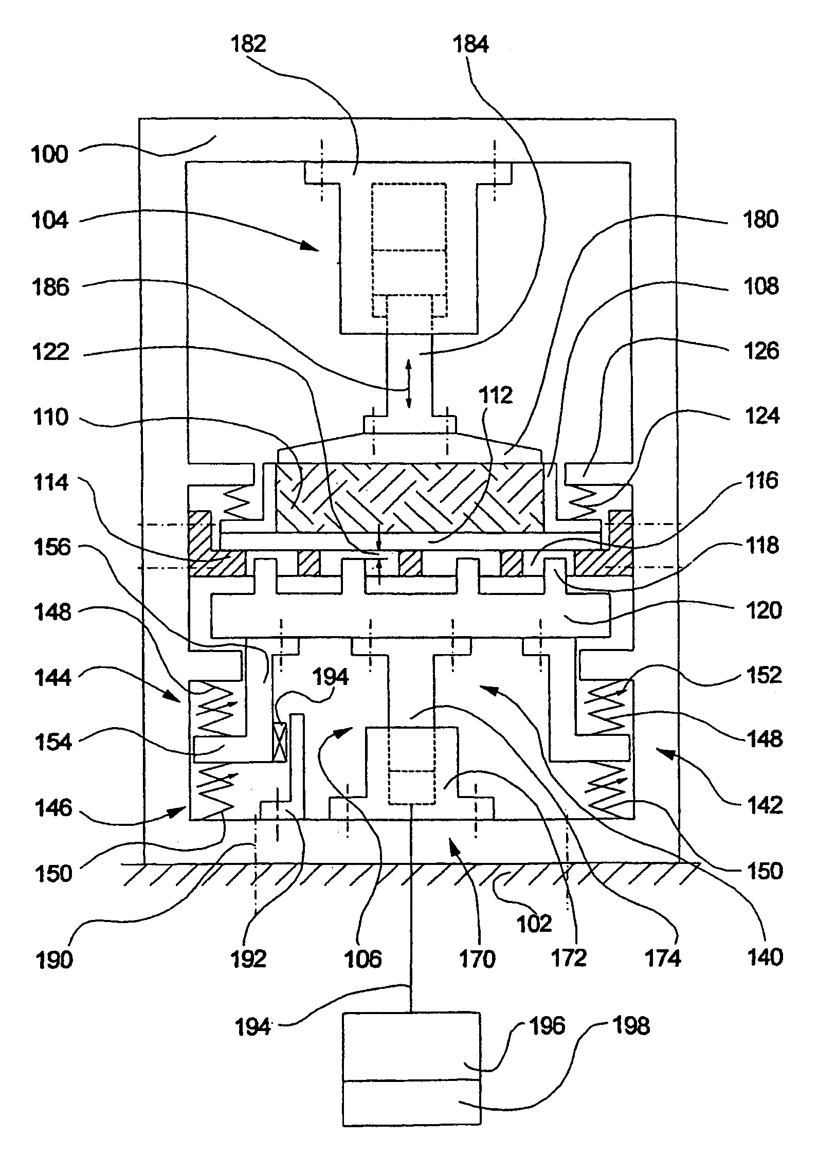
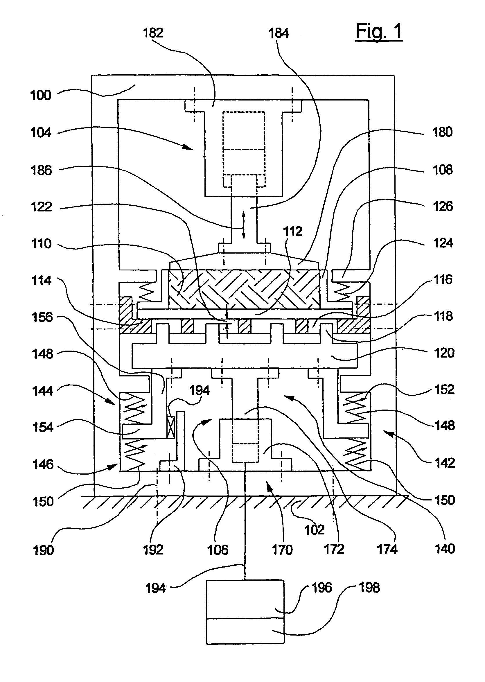
[0034]In FIG. 1, 100 is the frame of the compacting device, which stands on the foundation 102 and by which the forces to be transferred from the pressing device 104 and from the exciter device 106 are supported against one another. The frame may in this case be firmly connected to the foundation, which is symbolically represented by the lines 190, although in the case of a small mass of the frame considerable exciter forces have to be transferred to the foundation. The molded body 110 enclosed in the mold cavity of the molding box 108 lies with its underside on a pallet 112. The pallet itself rests on a baffle bar 114, which is fastened to the frame 100 (and for the sake of clarity identified by shading) and which is provided with clearances 116, through which the impact bars 118 of the vibrating table 120 can reach and, in the oscillating movement of the vibrating table, strike against the underside of the pallet after overcoming the air gap 122. The molding box 108 resting on the...


PUM

PropertyMeasurementUnit
natural frequencyaaaaaaaaaa
frequenciesaaaaaaaaaa
phase angleaaaaaaaaaa

Abstract

Apparatus and method for carrying out compaction operations on molded bodies that consist of granular materials and are placed on pallets, the compaction being achieved by impact of a vibrating table on the underside of the pallet. The vibrating table, together with a spring system forms a mass-spring system, which acts as a vibrator capable of oscillation that is excited by an excitation device to produce forced vibrations. The spring system, together with the system mass, is designed to develop at least one individual frequency within the range of the compaction frequency, whereby it is also possible to adjust the individual frequency gradually or continuously. This, together with the fact that the excitation frequency can be adjusted, allows the vibrator to be operated partially or completely in resonance mode over the whole frequency range of the compaction.

Description

CROSS-REFERENCE TO RELATED APPLICATIONS[0001]This is the national stage of International Application No. PCT / DE01 / 02266 filed Jun. 19, 2001 which claims priority from German Patent Application No. 100 56 063.6 Filed Nov. 11, 2000, German Patent Application No. 100 55 904.2 Filed Nov. 12, 2000, German Patent Application No. 100 60 860.4 Filed Dec. 6, 2000, and German Patent Application No. 101 06 910.3 Filed Feb. 13, 2001.BACKGROUND OF THE INVENTION[0002]The invention relates to a compacting device operated with vibration oscillations for molding and compacting molding materials in mold cavities of molding boxes to form molded bodies and to a method of using the compacting device, the molded bodies having an upper side and an underside, via which the compacting forces are introduced. In the case of this method, before the compacting operation, the molding material is located in the mold cavities initially as a volume mass of loosely coherent granular constituents, which are molded in...

Claims


Application Information

Patent Timeline
Patent Type & Authority Patents(United States)
IPC IPC(8): B28B1/087B06B1/10B06B1/16B28B3/02B30B11/02
CPCB06B1/10B30B11/022B28B3/022B06B1/166
Inventor BALD, HUBERT
Owner GEDIB ING & INNOVATIONSBERATUNG
Why Eureka
Try Eureka