
GMR module

a technology of gmr modules and components, applied in the field of components, can solve problems such as the destruction of connections or parts of the connection system

Inactive Publication Date: 2006-04-11
ELEKTRONIK
View PDF17 Cites 4 Cited by
  • Summary
  • Abstract
  • Description
  • Claims
  • Application Information

AI Technical Summary

Benefits of technology

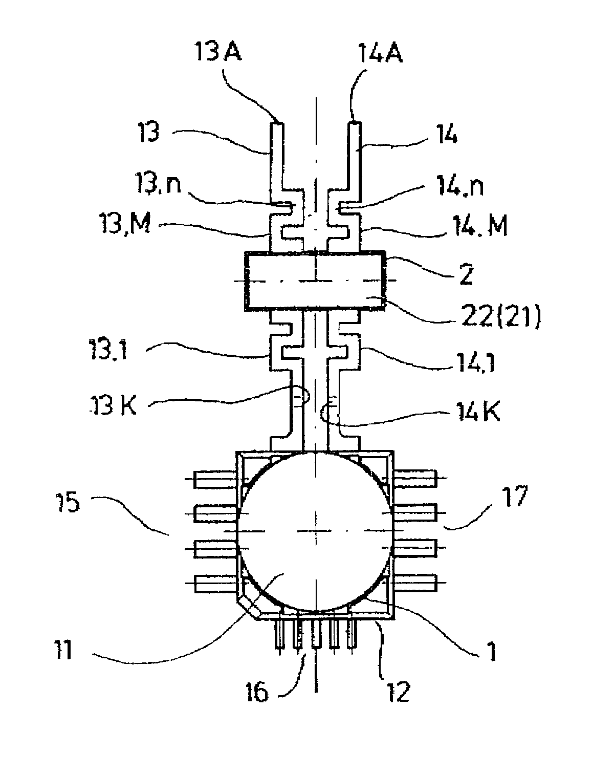
"The present invention is about improving the durability of a component called a Giant Magnet-Resistor (GMR) module. The invention achieves this by using a meander group with at least one meander element in both first and second connection elements between the component cell and the straight function connection element. This mechanical decoupling prevents external mechanical forces from affecting the GMR unit, avoiding the occurrence of cracks. The capacitor unit can be soldered onto the meander group, which is a low-cost and effective connection. The meander elements can be in different shapes, such as rectangular, sinusoidal, sawtooth, or damped oscillation curve. An expansion section can be added between the meander group and the component cell for further mechanical decoupling and proper positioning of the connection. The shape of the connection elements depends on the specific installation and manufacturing operations involved. The component cell can be a Giant Magneto-Resistor cell or any other shape."

Problems solved by technology

The disadvantage is that this connection system, particularly during connection of the straight connection elements with other parts and elements of the overall system with other parts and elements, is subjected to forces that may lead to destruction of the connections or of parts of the connection system.

Method used


Image

  • GMR module
  • GMR module
  • GMR module

Examples


Embodiment Construction

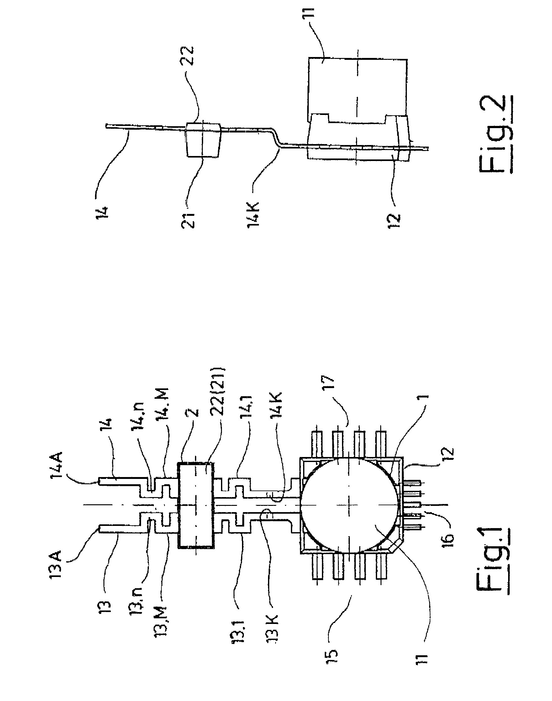
[0020]The preferred embodiments of the present invention will now be described with reference to FIGS. 1 and 2 of the drawings. Identical elements in the various figures are designated with the same reference numerals.

[0021]As FIGS. 1 and 2 show, a GMR module consists of:[0022]A Giant Magneto-Resistor (GMR) cell 1, and[0023]A capacitor unit 2.

[0024]The GMR cell 1 includes a GMR housing element 12, on which a GMR element is mounted. The GMR element is a magnetic resistor with reluctance Rm. In a magnetic circuit, the reluctance is the quotient of the magnetic voltage V divided by the magnetic flux φ, i.e.:

[0025]Rm=Vφ

[0026]The inverse value of the magnetic resistance is denoted as magnetic conductance Λ.

[0027]The magnetic resistor, also known as a magneto-resistor (field plate), is used to achieve high signal voltage levels under low-current conditions. With such a component, one is challenged to make the relative resistance alteration as large as possible, and to make these resistors...


PUM


Abstract

So that the parts and connections of a component, particularly a Giant Magneto-Resistor, may withstand external forces, a meander group (13M, 14M) with at least one meander element (13.1, . . . , 13.n, 14.1, . . . , 14.n) is positioned in both connection elements (13, 14) between a component cell (1) and the straight functional connection element (13A, 14A). A capacitor unit (2) is mounted on the meander group (13M) of the first connection element (13) and on the meander group (14M; of the second connection element (14).

Description

BACKGROUND OF THE INVENTION[0001]The invention relates to a component, particularly a Giant Magnet-Resistor device, consisting of at least[0002]A component cell that includes at least two connection elements that end in an essentially straight function connection element, and[0003]A capacitor unit mounted on both connection elements.[0004]A Giant Magnet-Resistor (GMR) module consists of a GMR cell with two essentially straight connection elements. A capacitor is connected to both connection elements.[0005]The disadvantage is that this connection system, particularly during connection of the straight connection elements with other parts and elements of the overall system with other parts and elements, is subjected to forces that may lead to destruction of the connections or of parts of the connection system. Since the GMR cell is relatively small geometrically, it may be the first active element to be destroyed.SUMMARY OF THE INVENTION[0006]The object of the present invention is ther...

Claims


Application Information

Patent Timeline
Patent Type & Authority Patents(United States)
IPC IPC(8): H01L43/00G11C5/00G11C11/14G11C11/16H10N50/80
CPCB82Y25/00G01R33/0005H01L43/02G01R33/093G11C11/14G01R33/091H10N50/80
Inventor APEL, PETER
Owner ELEKTRONIK
Learn More