

Pattern antenna
a technology of antennas and antennas, applied in the field of antennas, can solve the problems of limiting the miniaturization and thinning of antennas, and narrow frequency bandwidth of antennas
- Summary
- Abstract
- Description
- Claims
- Application Information
AI Technical Summary
Benefits of technology
Problems solved by technology
Method used
Image

Examples
first embodiment
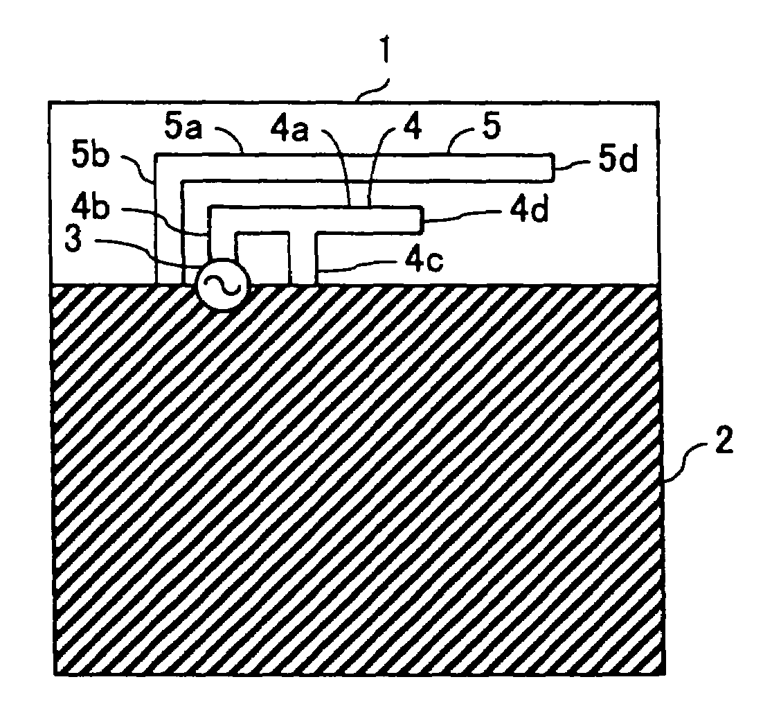
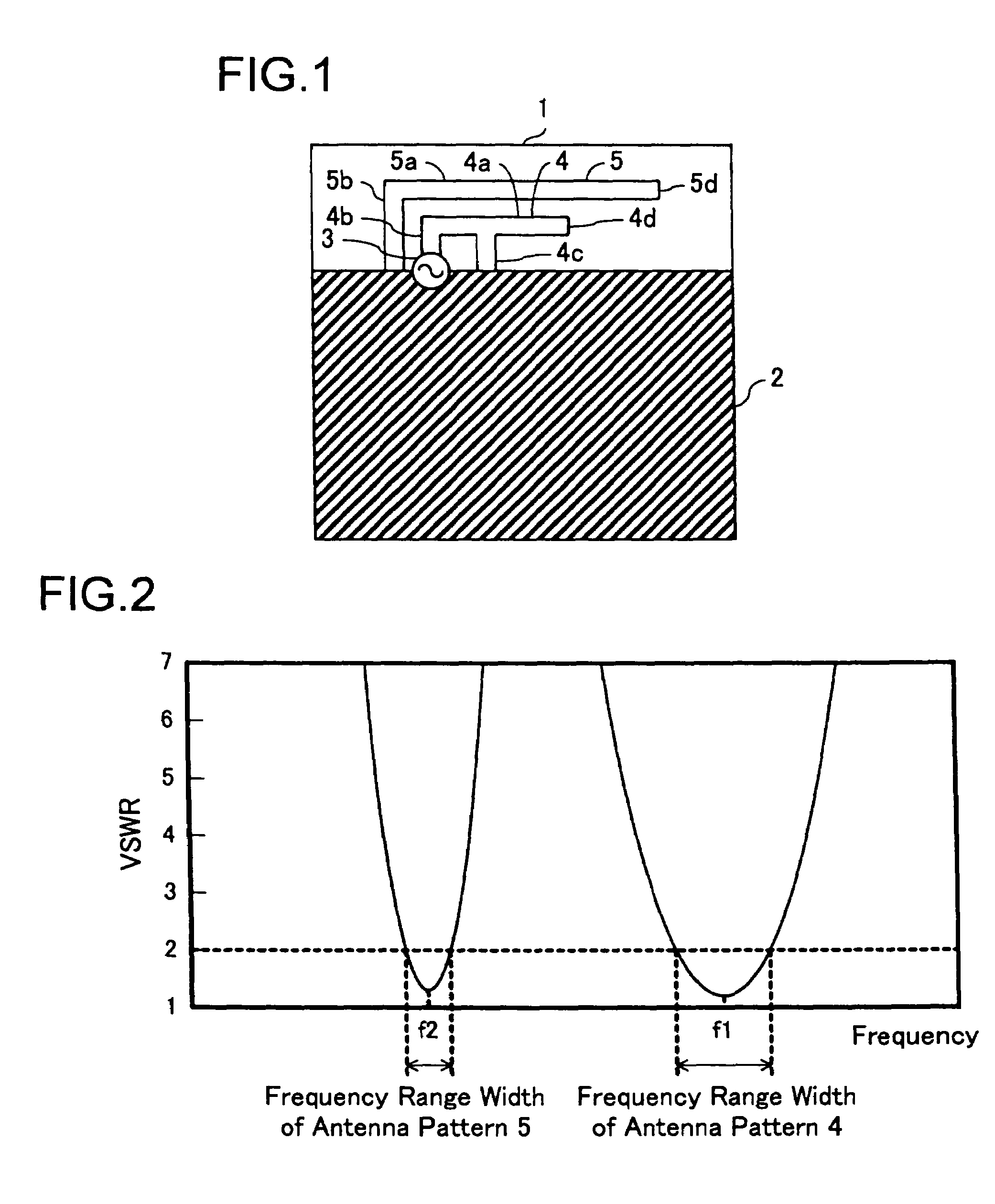
[0058]the present invention will be described below with reference to the drawings. FIG. 1 is a diagram showing the obverse-side surface of the pattern antenna of this embodiment. FIG. 2 is a graph showing the frequency response of the voltage standing wave ratio (VSWR) of the pattern antenna of this embodiment.
[0059]The pattern antenna of this embodiment is composed of an inverted-F-shaped antenna pattern 4 and an inverted-L-shaped antenna pattern 5 that are formed by a metal foil on the surface of a printed circuit board 1 shown in FIG. 1; and a ground pattern 2. The inverted-F-shaped antenna pattern 4 and the inverted-L-shaped antenna pattern 5 are formed in an edge portion of the printed circuit board 1 which has other circuit patterns and the like also formed thereon.
[0060]The inverted-F-shaped antenna pattern 4 formed on the surface of the printed circuit board 1 consists of an elongate pattern 4a that is formed in parallel with the edge of circumference of the ground pattern ...
seventh embodiment
[0106]The pattern antenna of this embodiment is composed of a loop-type antenna pattern 7 and a ground pattern 2a that are formed by a metal foil on a surface of the printed circuit board 1 shown in FIG. 19A; and an inverted-L-shaped antenna pattern 5 and a ground pattern 2b that are formed on the reverse-side of the printed circuit board 1 shown in FIG. 19B. Here, different from the pattern antenna of the seventh embodiment, the elongate pattern 5a and the conductor pattern 5b of the inverted-L-shaped antenna pattern 5 and the elongate pattern 7a and the conductor pattern 7b of the loop-type antenna pattern 7 are installed, overlapping each other with the printed circuit board 1 sandwiched in between.
[0107]With this construction as described above, the inverted-L-shaped antenna pattern 5 and the loop-type antenna pattern 7 are not formed on the same surface but isolated by the printed circuit board 1, and as a result, their locations can be adjusted in a direction in parallel with ...
eighth embodiment
[0108]In this embodiment, the pattern antenna has the inverted-L-shaped antenna pattern and the loop-type antenna pattern formed on the observe-side surface and the reverse-side surface of the printed circuit board respectively. However, same as the eighth embodiment, a pattern antenna may be so constructed as to have an inverted-L-shaped antenna pattern and a loop type antenna pattern overlap each other on different layers of the printed circuit board consisting of a plurality of layers.
PUM
 Abstract
Description
Claims
Application Information