Optical recording device and optical recording method, control program for the optical recording device, and computer-readable recording medium recording the control program

a recording device and recording control technology, applied in the field of optical recording devices and optical recording methods for recording information in recording mediums, can solve the problems of preventing uniform recording, affecting the quality of recording information, and difficult to realize high-density recording, etc., and achieves the effect of superior accuracy and short tim

Inactive Publication Date: 2006-04-11
SHARP KK
View PDF10 Cites 8 Cited by
  • Summary
  • Abstract
  • Description
  • Claims
  • Application Information

AI Technical Summary

Benefits of technology

[0011]It is an object of the present invention to provide an optical recording device and an optical recording method which are capable of performing recording even when a plurality of tracks are differently characterized as, for example, in the case of lands and grooves, by setting an optimum

Problems solved by technology

There has been a particular problem that fluctuation in size of a record mark is caused by variation in such recording conditions as a recording light quantity of a light beam to be emitted to an optical disk, a recording magnetic field strength of an externally applied magnetic field to be applied to a magneto-optical disk, and the like, thereby preventing uniform recording and making it difficult to realize high-density recording.
However, a problem is that a difference may occur in optimum recording conditions even in the case where a land and a groove adjacent to each other are compared, which is due to (i) variation in a ratio of a land width to a groove width, (ii) a difference in thermal conductivity from the land to the groove and vice versa, and (iii)

Method used


Image

  • Optical recording device and optical recording method, control program for the optical recording device, and computer-readable recording medium recording the control program
  • Optical recording device and optical recording method, control program for the optical recording device, and computer-readable recording medium recording the control program
  • Optical recording device and optical recording method, control program for the optical recording device, and computer-readable recording medium recording the control program

Examples


Embodiment Construction

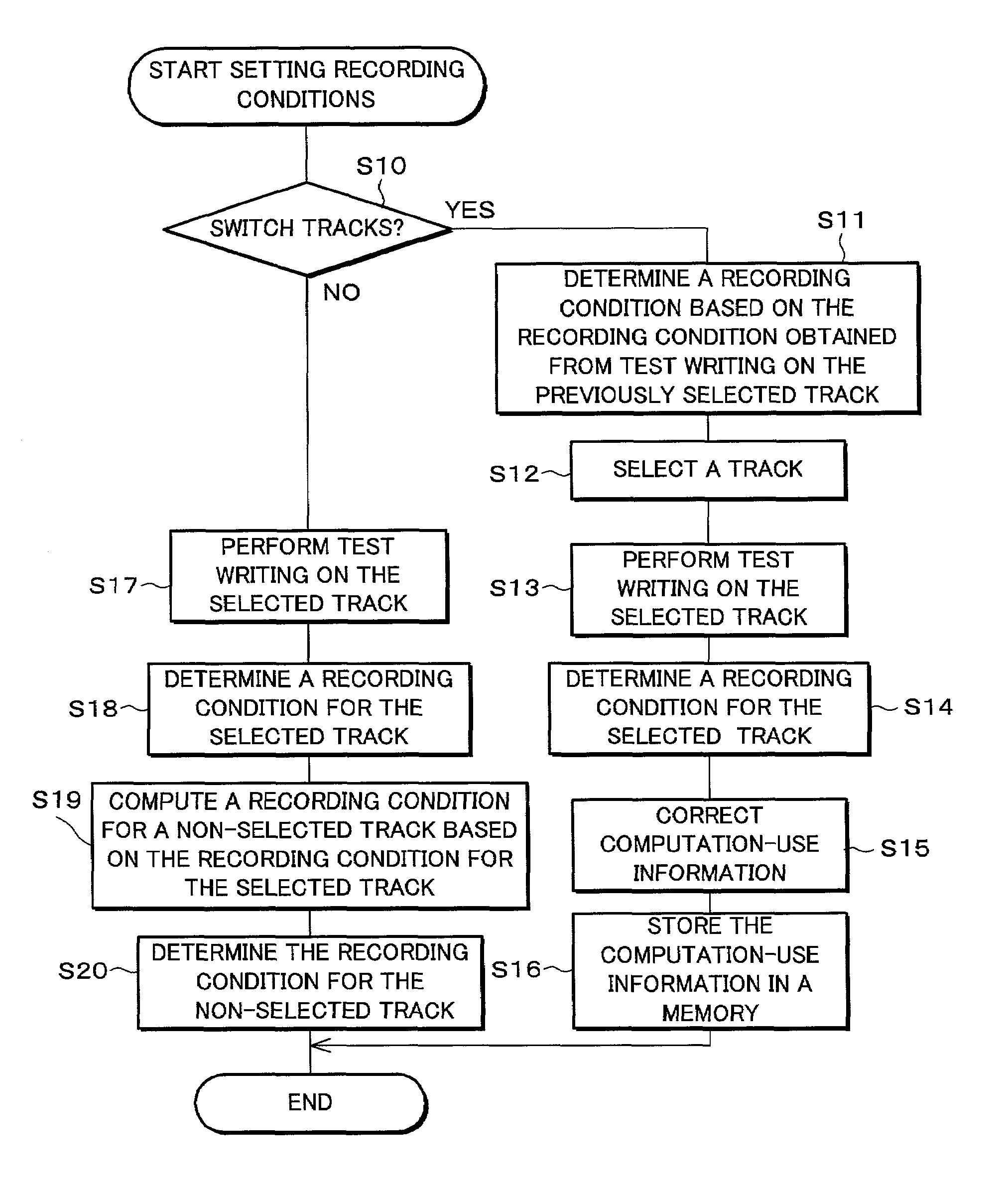
[0030]The following will explain one embodiment of the present invention with reference to FIGS. 1 through 7.

[0031]Note that, in the present embodiment, explanation will be made with an example of magneto-optical recording. Further, for ease of explanation, an explanation of the optimization of recording conditions will be made through a case where the optimization of a recording light quantity in magnetic field modulation recording is performed.

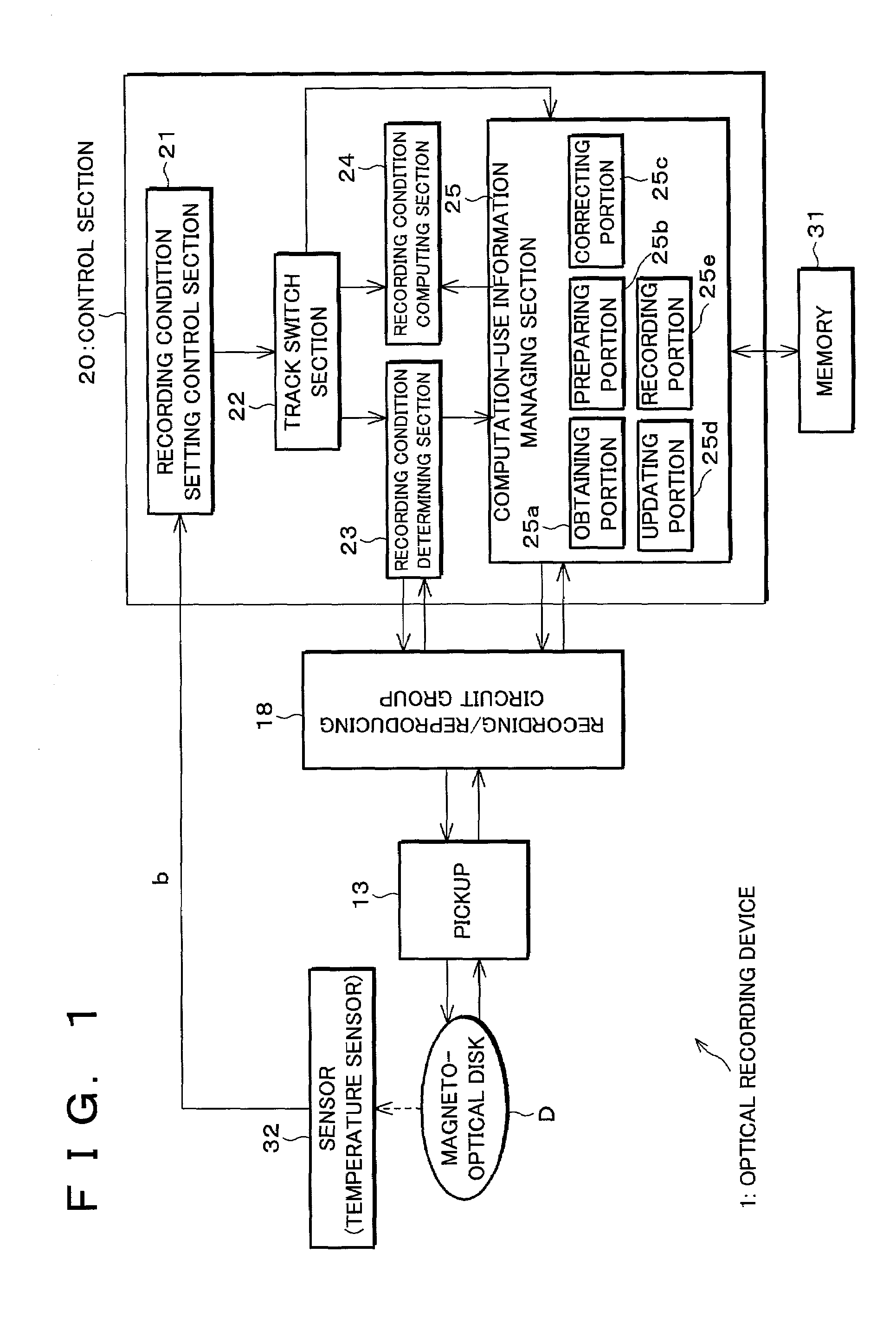
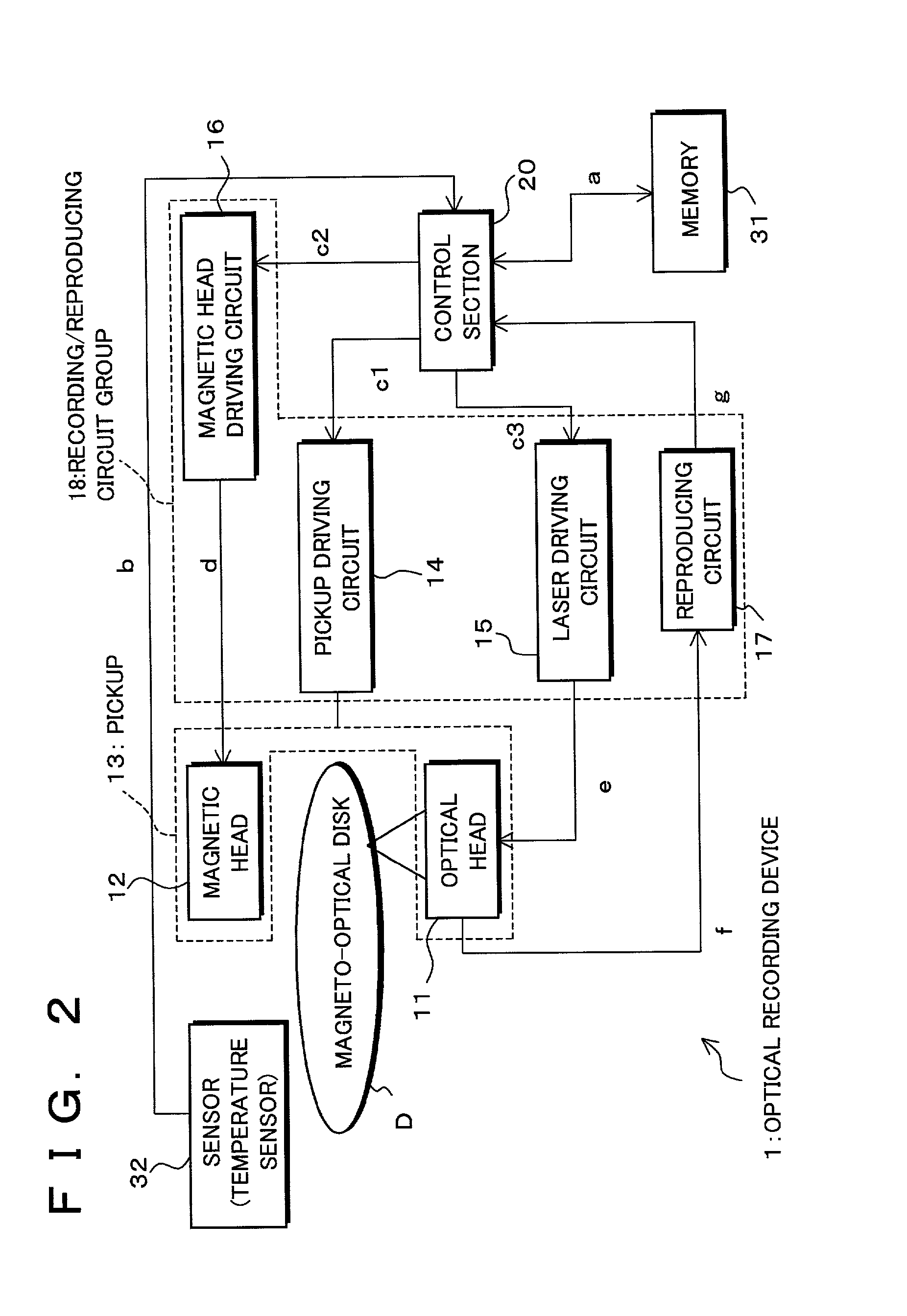
[0032]FIG. 2 is a block diagram schematically showing an arrangement of an optical recording device 1 according to the present embodiment.

[0033]A magneto-optical disk D to be loaded to the optical recording device 1 is an optical recording medium including a substrate provided with a guiding track made up of a groove which is the guiding track and a land which is a convex portion, where both the land and the groove are recording / reproducing tracks.

[0034]In the optical recording device 1, a control section 20, via a pickup driving circuit 14,...


PUM


Abstract

An optical recording device includes a recording condition determining section for determining recording conditions for a track by performing test writing with respect to the track which is, for example, either a land or a groove of a magneto-optical disk, a recording condition computing section for performing computation in accordance with computation-use information based on the recording conditions for the track so as to determine recording conditions for the other track, a track switch section for switching tracks to be used for test writing, and a computation-use information managing section for correcting the computation-use information based on respective results of test writing before and after the switch, thereby determining recording conditions for one of the tracks in short time by computation, while, because the computation-use information is corrected based on the results of test writing, improving accuracy in recording conditions obtained by computation.

Description

FIELD OF THE INVENTION[0001]The present invention relates to an optical recording device and an optical recording method for recording information in a recording medium, and in particular to an optical recording device and an optical recording method which are capable of stably optimizing respective recording conditions for a plurality of differently characterized tracks, as well as a control program for the optical recording device and a computer-readable recording medium in which the control program is recorded.BACKGROUND OF THE INVENTION[0002]In recent years, research on a high-density optical disk is growing in popularity. There has been a particular problem that fluctuation in size of a record mark is caused by variation in such recording conditions as a recording light quantity of a light beam to be emitted to an optical disk, a recording magnetic field strength of an externally applied magnetic field to be applied to a magneto-optical disk, and the like, thereby preventing un...

Claims


Application Information

Patent Timeline
IPC IPC(8): G11B7/00G11B7/004G11B7/0045G11B7/007G11B7/125G11B7/1267G11B11/105
CPCG11B7/0045G11B7/00718G11B11/10504G11B11/10595G11B7/1267G11B7/00736G11B2007/0013G11B7/004
Inventor ADACHI, YOSHIHISAMAEDA, SHIGEMI
Owner SHARP KK
Why Eureka
Try Eureka