Frame synchronizing signal detecting method for reducing occurrence of error synchronization before link of frame synchronizing signal is established

a frame synchronizing signal and detection method technology, applied in the direction of synchronizing signal speed/phase control, digital transmission, electrical equipment, etc., can solve the problems of deteriorating detection rate of frame synchronizing signal, long time to establish link, and frequent error synchronization, so as to achieve simple configuration, not greatly increased manufacturing cost and occupied volume

Inactive Publication Date: 2006-04-11
ALPS ALPINE CO LTD
View PDF6 Cites 2 Cited by
  • Summary
  • Abstract
  • Description
  • Claims
  • Application Information

AI Technical Summary

Benefits of technology

[0022]According to the configuration, if a function produced by the abovementioned means is achieved by the frame synchronizing signal detector, the frame sync

Problems solved by technology

If the detection precision of a frame synchronizing signal is set so that it is higher than the regular detection precision, there is an advantage in that error synchronization is reduced and the establishment of a stable link can be achieved before a frame synchronizing signal link is established (a link is tried), however, there is a disadvantage in that after a frame synchronizing signal link is established, non-detection due to slight noise superimposed on data and disturbance is often caused and the detection rate of a frame synchronizing signal is deteriorated.
In the meantime, if the detection precision of a frame synchronizing signal is set so that it is lower than the regular detection precision, there is an advantage in that the occurrence of non-detection due to slight noise superimposed on data and disturbance is reduced and t

Method used


Image

  • Frame synchronizing signal detecting method for reducing occurrence of error synchronization before link of frame synchronizing signal is established
  • Frame synchronizing signal detecting method for reducing occurrence of error synchronization before link of frame synchronizing signal is established
  • Frame synchronizing signal detecting method for reducing occurrence of error synchronization before link of frame synchronizing signal is established

Examples


Embodiment Construction

[0025]Referring to the drawings, an embodiment of the invention will be described below.

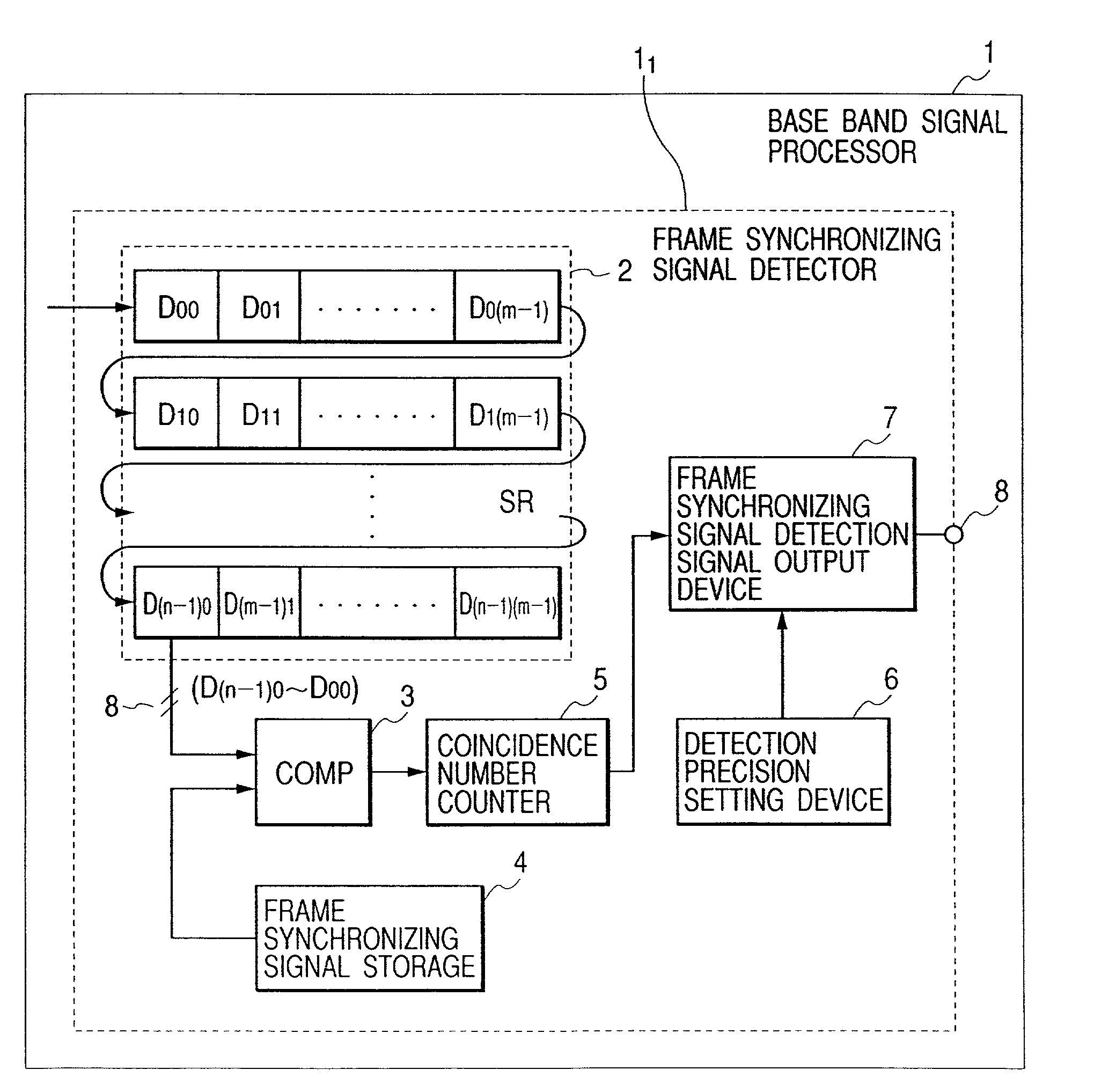
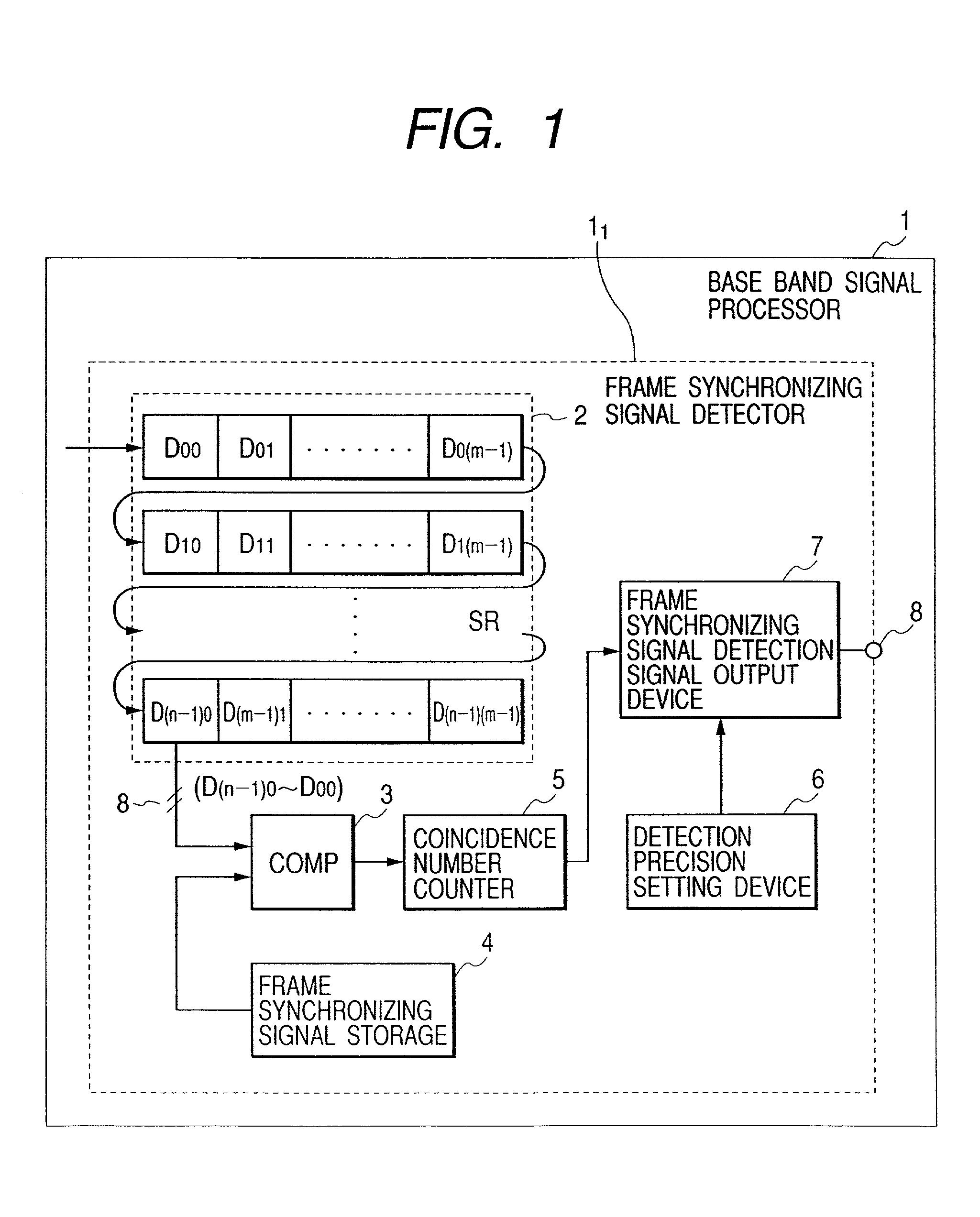
[0026]FIG. 1 shows one embodiment of a frame synchronizing signal detecting method according to the invention and is a block diagram showing the configuration of the main part of a frame synchronizing signal detector in a baseband signal processor of a data multiplexing transmitter-receiver.

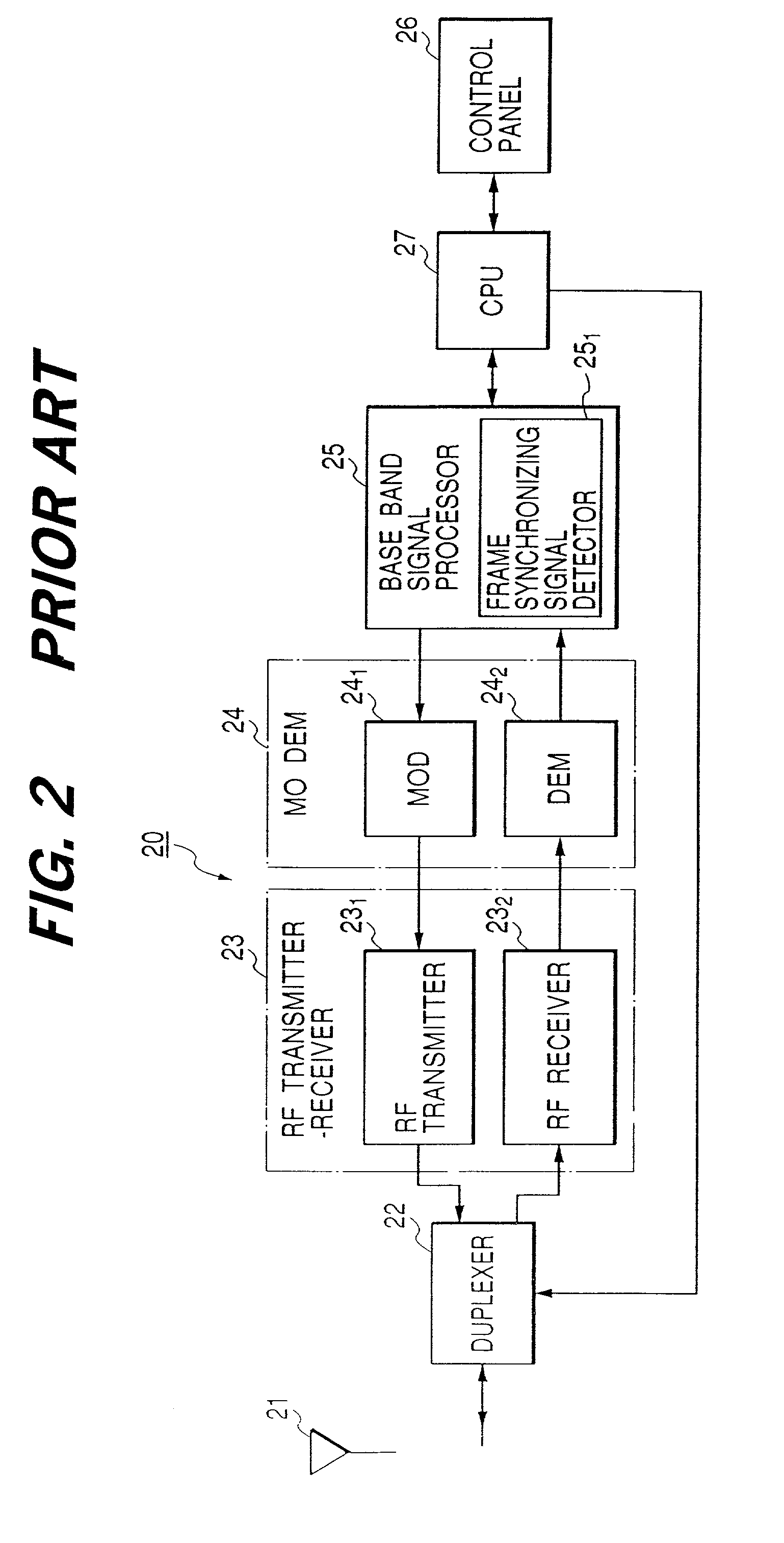
[0027]As shown in FIG. 1, as components except the baseband signal processor in the data multiplexing transmitter-receiver are substantially the same as those in a known data multiplexing transmitter-receiver shown in FIG. 2, they are not shown in FIG. 1.

[0028]As shown in FIG. 1, the frame synchronizing signal detector 11 in the baseband signal processor 1 includes a shift register (SR) 2 composed of m (an integer) rows the number of which is equal to a sampling rate (the number of data shift clocks) and n (an integer) columns for sequentially shifting received data, a comparator (COMP) 3 that detects the numb...


PUM


Abstract

A frame synchronizing signal detecting method according to the invention is used in a data multiplexing transmitter-receiver which is provided with a transmitter-receiver that transmits and receives at least a radio-frequency signal, a modulator-demodulator that converts the radio-frequency signal to a baseband signal and vice versa and a baseband signal processor that processes the baseband signal and in which the baseband signal processor is provided with a frame synchronizing signal detector, and when a frame synchronizing signal included in received data is detected, the frame synchronizing signal detector sets the detection precision of the frame synchronizing signal before a frame synchronization link is established to a value higher than regular detection precision and sets the detection precision of the frame synchronizing signal after the frame synchronization link is established to a value lower than the regular detection precision.

Description

[0001]This application claims the benefit of priority to Japanese Patent Application No. 2001-033992, herein incorporated by reference.BACKGROUND OF THE INVENTION[0002]1. Field of the Invention[0003]The present invention relates to a frame synchronizing signal (a unique word) detecting method, particularly relates to a frame synchronizing signal detecting method used for a data multiplexing transmitter-receiver of achieving the stable establishment of a link by enhancing the detection precision of a frame synchronizing signal before the link of a frame synchronizing signal is established and of preventing non-detection due to noise and disturbance by lowering the detection precision of a frame synchronizing signal after the link of a frame synchronizing signal is established.[0004]2. Description of the Related Art[0005]Generally, a frame synchronizing signal (also called a unique word or a flag) having a specific bit pattern is added to the head of data included in each data packet,...

Claims


Application Information

Patent Timeline
IPC IPC(8): H04L7/00H04J3/06H04L7/08
CPCH04J3/0608
Inventor SUZUKI, KATSUJI
Owner ALPS ALPINE CO LTD
Why Eureka
Try Eureka