Optical distribution device and light waveguide connector cable

a technology of optical distribution device and light waveguide, which is applied in the direction of optics, fibre mechanical structures, instruments, etc., can solve the problem of becoming more and more difficult to monitor the patch panel

Inactive Publication Date: 2006-04-11
CCS TECH INC
View PDF1 Cites 108 Cited by
  • Summary
  • Abstract
  • Description
  • Claims
  • Application Information

AI Technical Summary

Benefits of technology

[0022]The code memory device can be freely attached, for example glued on or screwed on, to the outside of the connecting device. It is preferred to accommodate the code memory device in a housing that is for its part attached to the connecting device, in particular to its outside. The housing of the code memory device can be provided in one integral piece with the housing of the connecting device, it being possible for the code memory device, that is to say the memory chip, also to be encapsulated directly into the housing. However, ...

Problems solved by technology

Given a rising number of connections, it become...

Method used


Image

  • Optical distribution device and light waveguide connector cable
  • Optical distribution device and light waveguide connector cable
  • Optical distribution device and light waveguide connector cable

Examples


Embodiment Construction

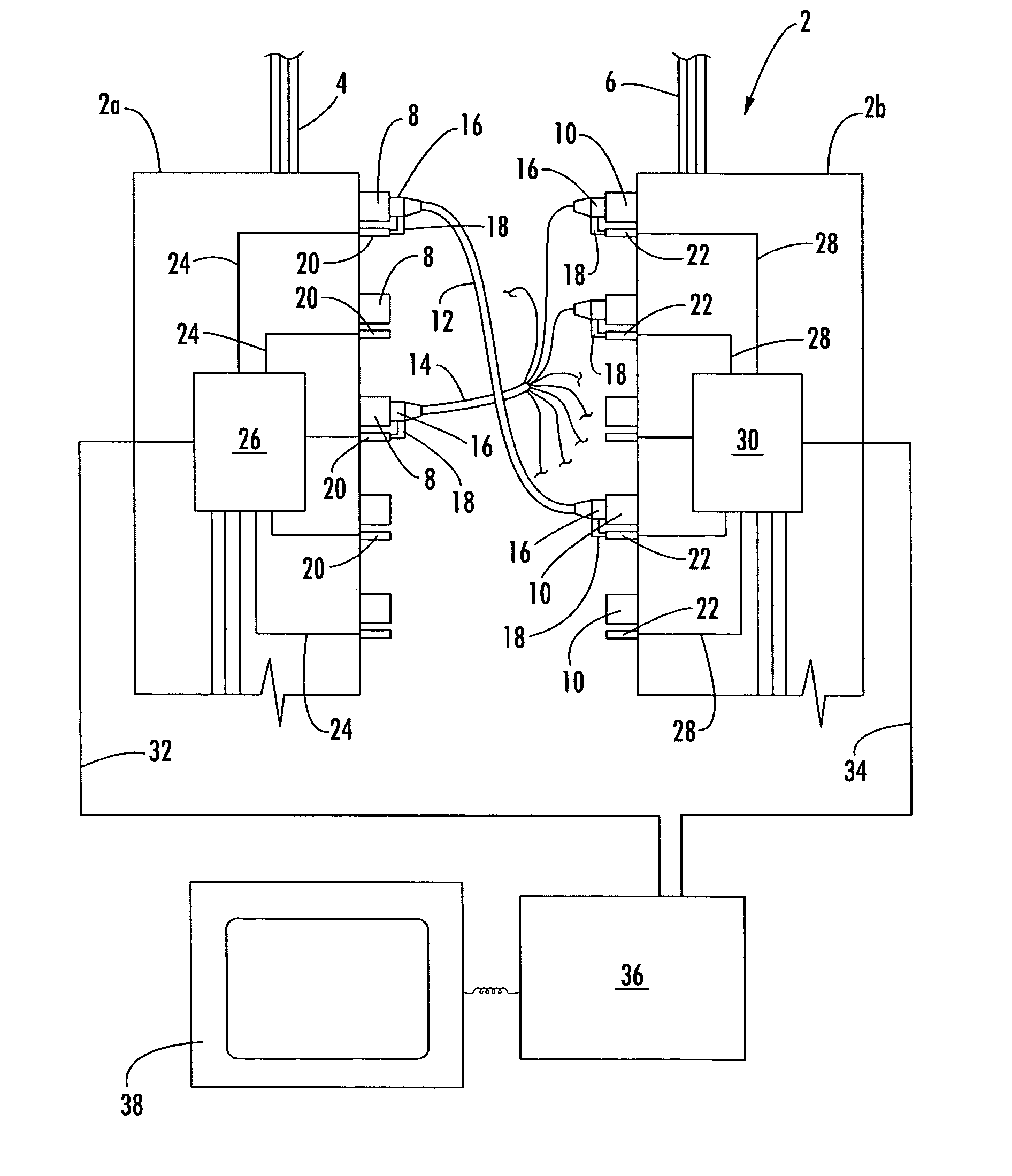
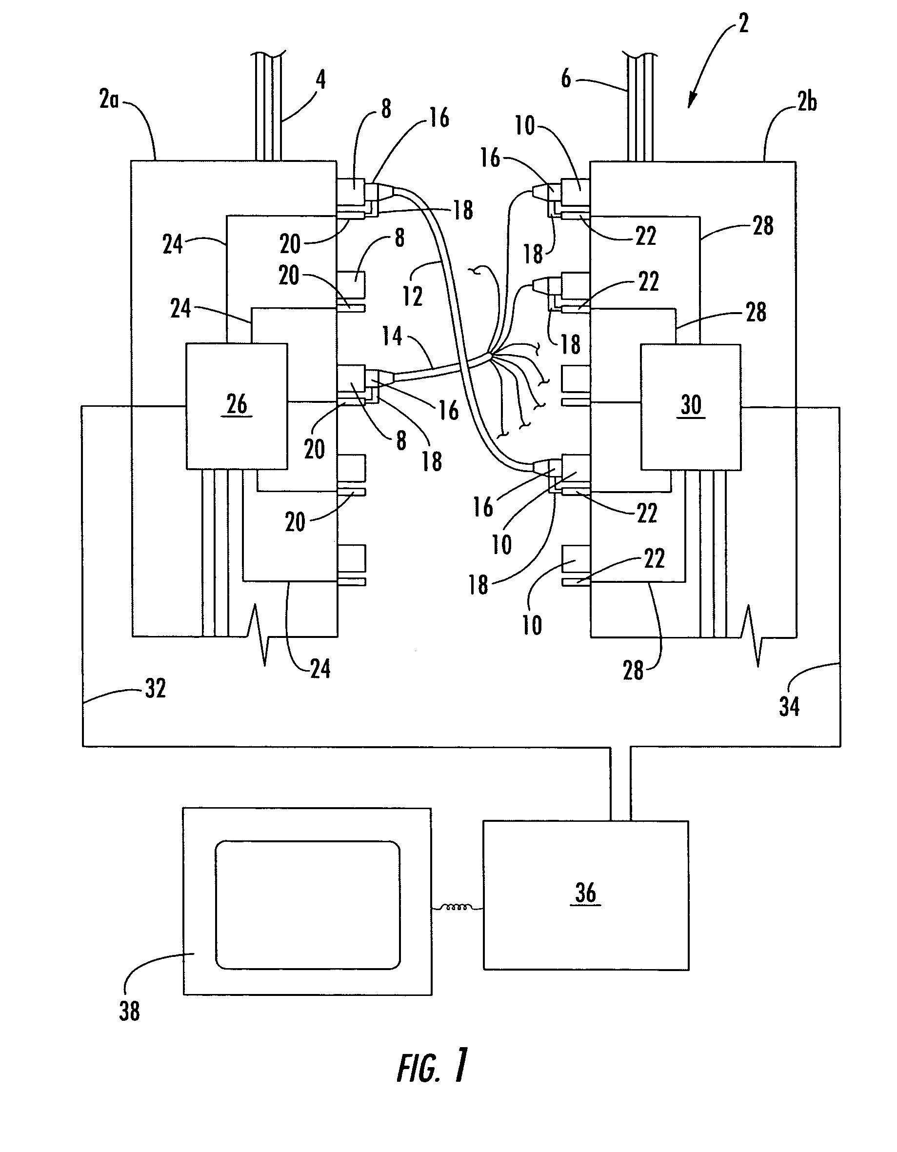
[0032]FIG. 1 illustrates schematically a module 2 of a multimodule, optical distribution device in accordance with one embodiment of the invention. The module 2 of the optical distribution device has a first submodule 2a, to which incoming optical lines 4 are connected, and a second submodule 2b, to which the outgoing optical lines 6 are connected. The incoming optical lines 4 are connected for this purpose to first connecting points 8 that are provided at the first submodule 2a and are designed here in the form of sockets. The outgoing lines 6 are connected to second connecting points 10, which are arranged at the second submodule 2b and are likewise provided as sockets.

[0033]Light signals are led up to the distribution device via the incoming optical lines 4; the light signals incoming at the distribution device are passed on via the outgoing optical lines 6.

[0034]For the purpose of distributing the light signals conducted by the incoming lines 4, the distribution device has a plu...


PUM


Abstract

An optical distribution device has first connector points for the connection of incoming light waveguide cables, second connector points for the connection of outgoing light waveguide cables and at least one light waveguide connector cable having at least one connecting device on one or both ends for connecting at least one of the first connector points to at least one of the second connector points. Each connection device is provided with an electrical code memory device for storing an identification code and each of the first and second connector points are provided with an electrical code reader device connected to the associated code memory device for reading the identification code when the associated connector device is connected to one of the connector points. A controller is connected to the code reader device for evaluating the identification code to identify the optical connection effected by the light waveguide connector cable.

Description

CROSS REFERENCE TO RELATED APPLICATION[0001]This application is a National application claiming priority to International Application No. PCT / EP02 / 04089 filed on Apr. 12, 2002, which claims priority to German Patent Application No. 101 26 351.1, filed on May 30, 2001.FIELD OF THE INVENTION[0002]The invention relates to an optical distribution device and a light waveguide connector cable for use in an optical distribution device.BACKGROUND OF THE INVENTION[0003]In a fiber optic patch panel, the individual incoming and outgoing fibers are connected to one another by means of patch cords. Here, incoming fibers are understood as those fibers via which light signals are sent in the direction of the patch panel; the light signals are passed on from the patch panel via the outgoing fibers. Furthermore, the signal direction determines in this case whether a fiber is an incoming or outgoing fiber, that is to say the respective fiber is an incoming fiber if data signals are sent to the distri...

Claims


Application Information

Patent Timeline
IPC IPC(8): G02B6/36G02B6/38G02B6/44
CPCG02B6/3895G02B6/4472G02B6/4452
Inventor FROHLICH, FRANZ-FRIEDRICHSPENDE, PETER
Owner CCS TECH INC
Why Eureka
Try Eureka