Developing device and an image forming apparatus including the same

a development device and image forming technology, applied in the field ofdeveloper carriers, can solve the problems of image quality rank drop, delay in development, image quality degrade from that of a wide roller case, etc., and achieve the effect of high quality

Active Publication Date: 2006-04-11
RICOH KK
View PDF27 Cites 17 Cited by
  • Summary
  • Abstract
  • Description
  • Claims
  • Application Information

AI Technical Summary

Benefits of technology

[0019]Another object of the present invention is to provide a developer carrier having a high magnetic force and at a low manufacturing cost.
[0020]Another object of the present invention is to provide a developer carrier having a high image quality and at a low manufacturing cost.
[0021]Another object of the present invention is to provide a developer carrier having construction advantageous against carrier deposition while keeping the high-image quality.
[0024]Another object of the present invention is to provide an image forming apparatus equipped with the above-mentioned developing device or the process cartridge, and capable of forming a high quality image.

Problems solved by technology

This is caused by the fact that the development is delayed in relation to the change of the latent image because the movement of the toner in the developer toward the thickness direction of the developer in the developing region takes time.
(1) A proper half-value width varies with the outer diameter of the developing roller.
(2) A difference occurs in the image quality rank, even with the same half-value width. Or, even if the half-value width is narrow, the image quality is degraded from that of a wide roller case.
The above problem (1) is considered to be caused by the fact that the larger the outer diameter of the developing roller is, the wider the width of the nip for development is, with the same half-value width.

Method used


Image

  • Developing device and an image forming apparatus including the same
  • Developing device and an image forming apparatus including the same
  • Developing device and an image forming apparatus including the same

Examples


embodiment 1

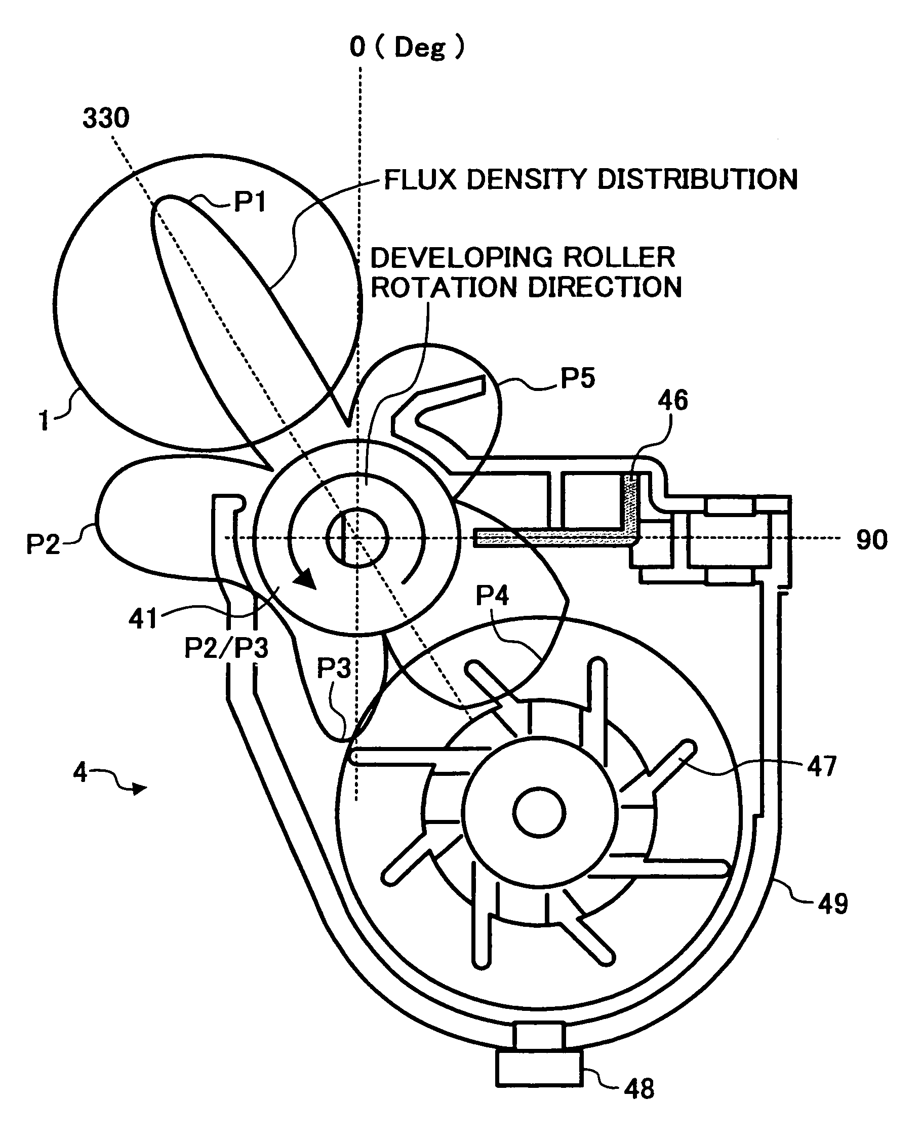
[0067]In the developing device 4 of such a construction of the present embodiment 1, since the developing roller 41 of the SLIC developing system is used, the width of the nip for development is narrowed to shorten moving time of the toner of the magnetic brush from the drum 1 side to the developing roller 41 side, when the magnet brush rubs a non-image part on the drum 1 in the developing region.

[0068]Also, a density of the magnet brush is heightened in order to make uniform a developing field and supplement lowering of contact probability of the developer caused by narrowing the width of the nip for development. In the SLIC developing roller of the present embodiment 1, the flux variation rate near the peak of the pole for development is high, which causes small and quick rising width of rising and falling of the magnet brush, therefore, a dense brush can be formed. In the developing roller of the present embodiment 1, since the flux density variation rate in the normal direction ...

embodiment 2

[0081]The basic construction of this developing roller 41 is same as shown in FIG. 12. The high magnetic force magnet block 45 is constituted in such a manner that it is formed smaller than the groove part of the approximately cylindrical magnet roller 43, and the high magnetic force magnet block 45 is buried in and fixed to the downstream side in the developer transporting direction in the above groove part. By this developing roller 41, the flux density distribution of the developing roller of the before-mentioned embodiment 2, can be easily obtained. For shifting the pole transition point in the upstream side to a further upstream side, a space in the upstream side of the groove part is enlarged in relation to the magnet block 45, and flux density distribution necessary for the developing device can be optionally set.

[0082]In the developing roller of the present invention, the rare earth-based magnet block 45 used being buried in the grooved part of the magnet roll 43, preferably...

embodiment 3

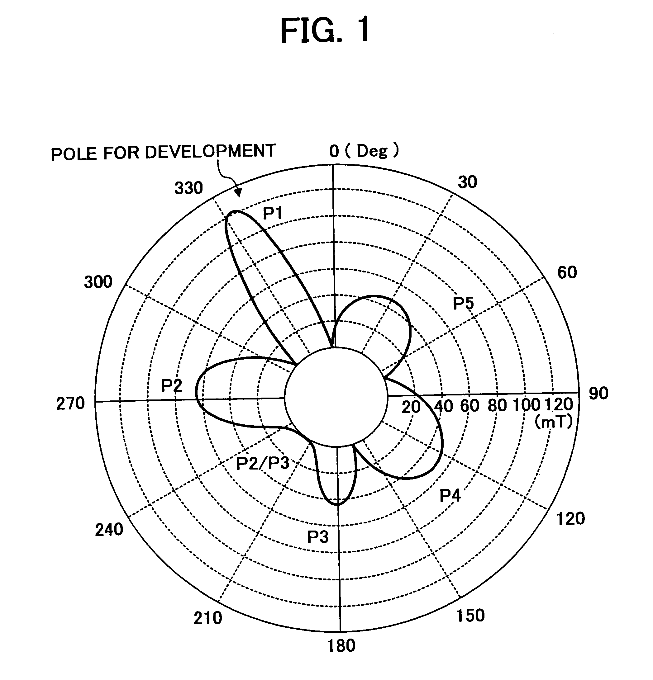
[0118]The developing roller of the embodiment 3 is an example of a developing roller which has a magnetic force distribution in the normal direction as shown in FIG. 21A, and characteristics of the flux density variation rate of the pole for development as shown by the curve 21(A) in FIG. 20A, and the flux density distribution of the pole for development as shown by the curve 21(A) in FIG. 20B, and satisfies the conditions of the half-value width of the flux density of 22° or less, and of the flux density variation rate in the normal direction of 4.0 mT / Deg or more.

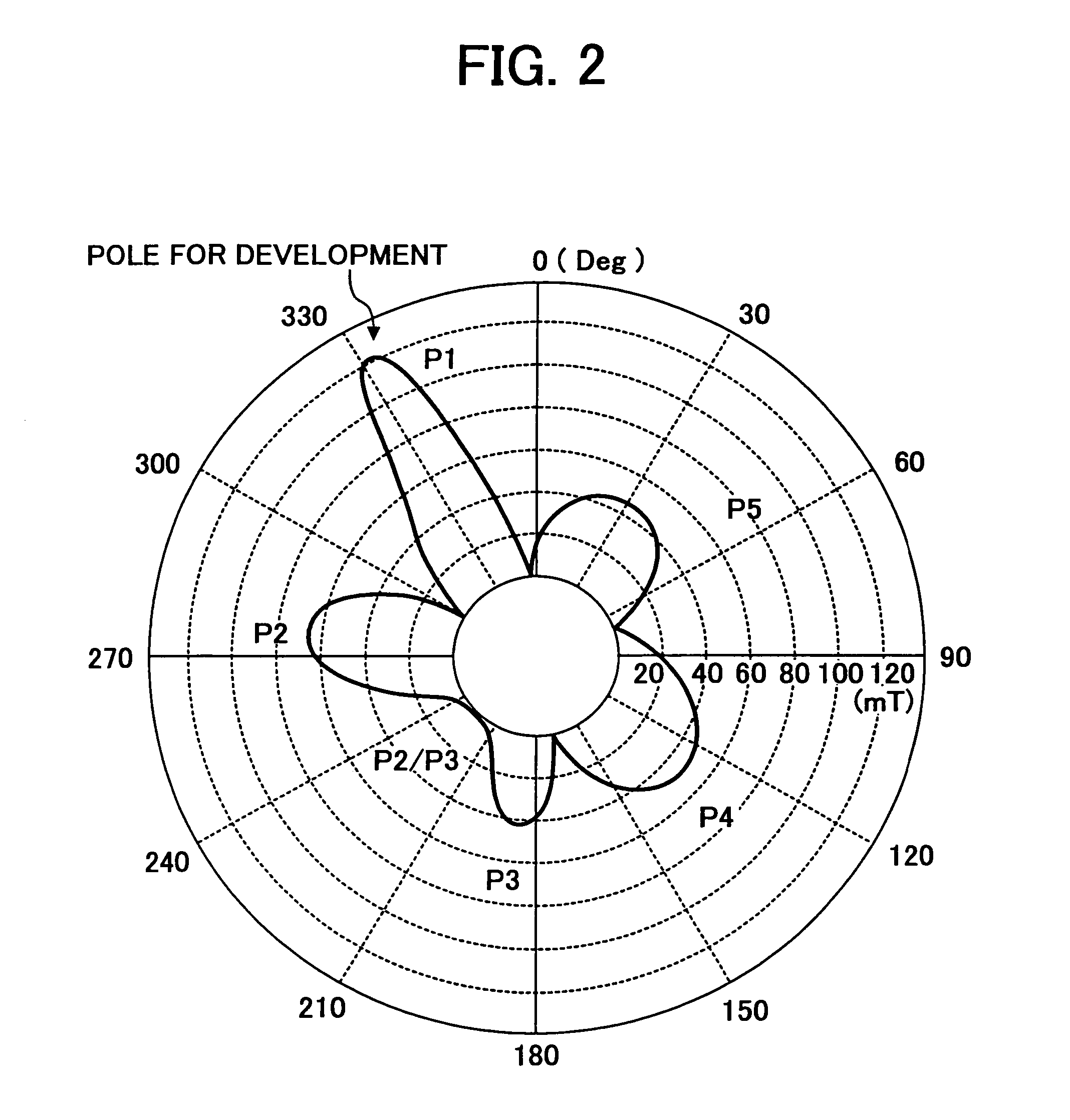
[0119]The developing roller of the embodiment 4 is an example of a developing roller which has a magnetic force distribution in the normal direction as shown in FIG. 21B, and characteristics of the flux density variation rate of the pole for development as shown by the curve 21(B) in FIG. 20A, and the flux density distribution of the pole for development as shown by the curve 21(B) in FIG. 20B, and satisfies the condition...


PUM

PropertyMeasurementUnit
particle sizeaaaaaaaaaa
widthaaaaaaaaaa
widthaaaaaaaaaa

Abstract

A developer carrier for an SLIC developing system includes a developing sleeve and a magnetic roll having a plurality of magnetic poles. A narrow development nip is formed by narrowing the width of a development pole forming a magnet brush and by narrowing a developer rising region in a developing region where a flux density attenuation ratio of the development pole is 40% or more. A half-value width of the flux density of the development pole is 22° or less and the flux density variation rate is 4.0 mT / Deg or more in a circumferential direction in a part where the flux density in at least half of that of a downstream side of a developer carrying direction from a peak magnetic force position of the development pole is 90% or less.

Description

BACKGROUND OF THE INVENTION[0001]1. Field of the Invention[0002]The present invention relates to a developer carrier including a developing roller for developing an electrostatic latent image on an image carrier such, as a photoconductive member, a developing device using the developer carrier, a process cartridge comprising the developing device, and a copier, facsimile apparatus, printer, plotter or similar image forming apparatus including these developing device or the process cartridge.[0003]2. Description of the Background Art[0004]In an image forming apparatus of an electrophotographic or electrostatic recording system including a copier, facsimile apparatus, printer or plotter, in general, an electrostatic latent image corresponding to image data is formed on an image, such as a drum-like or belt-like photoconductive member; the latent image on the image carrier is developed by a developer in a developing device as a toner image; the toner image is directly transferred to a ...

Claims


Application Information

Patent Timeline
Patent Type & Authority Patents(United States)
IPC IPC(8): G03G15/09H01F7/02
CPCG03G15/0921
Inventor KOETSUKA, KYOHTAIMAMURA, TSUYOSHIKAMOI, SUMIOKAMIYA, NORIYUKINARITA, KENJITATSUMI, KENZOKAKEGAWA, MIEKO
Owner RICOH KK
Why Eureka
Try Eureka