Curing light with engineered spectrum and power compressor guide

a technology of engineered spectrum and compressor guide, applied in the field of light, can solve the problems of inconvenient patient care, increased labor intensity, and increased difficulty in adjusting the speed of the compressor guide,

Inactive Publication Date: 2006-04-18
COLTENE WHALEDENT INC
View PDF11 Cites 54 Cited by
  • Summary
  • Abstract
  • Description
  • Claims
  • Application Information

AI Technical Summary

Problems solved by technology

Curing of the compound requires the liquid component to evaporate, causing the composite to harden.
In the past, curing has been accomplished by air drying, which has had the disadvantage of requiring significant time.
This time can greatly inconvenience the patient.
However, a problem with conventional halogen-based lights is that the lamp, filter and reflector degrade over time.
This degradation is particularly accelerated, for example, by the significant heat generated by the halogen lamp.
For example, this heat may cause filters to blister and cause reflectors to discolor, leading to reductions in light output and curing effectiveness.
While heat may be dissipated by adding a fan unit to the light, the fan may cause other undesired effects (for example, undesirably dispersing a bacterial aerosol that may have been applied by the dentist to the patient's mouth).
Alternate lamp technologies using Xenon and laser light sources have been investigated, but these technologies have tended to be costly, consumed large amounts of power and generated significant heat.
However, LEDs and LDs individually tend to produce relatively monochromatic light energy.
However, Cao falls short of disclosing an efficient means for combining light energy from monochromatic light sources of a few colors in order to produce a broad, continuous spectrum of light energy for curing a variety of composite materials.

Method used


Image

  • Curing light with engineered spectrum and power compressor guide
  • Curing light with engineered spectrum and power compressor guide
  • Curing light with engineered spectrum and power compressor guide

Examples


Embodiment Construction

[0021]The following detailed description includes a description of the best mode or modes of the invention presently contemplated. Such description is not intended to be understood in a limiting sense, but to be an example of the invention presented solely for illustration thereof, and by reference to which in connection with the following description and the accompanying drawing one skilled in the art may be advised of the advantages and construction of the invention.

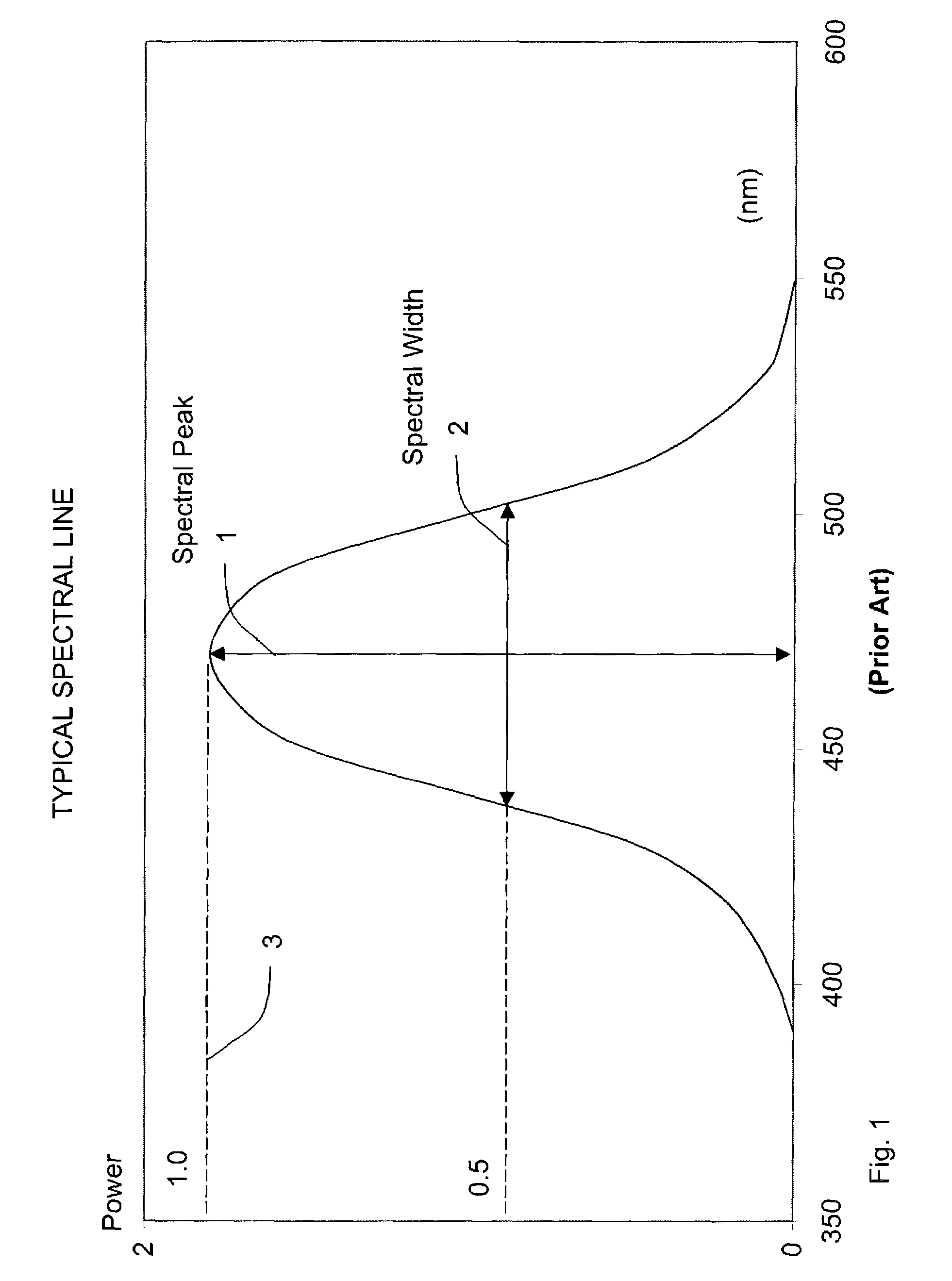
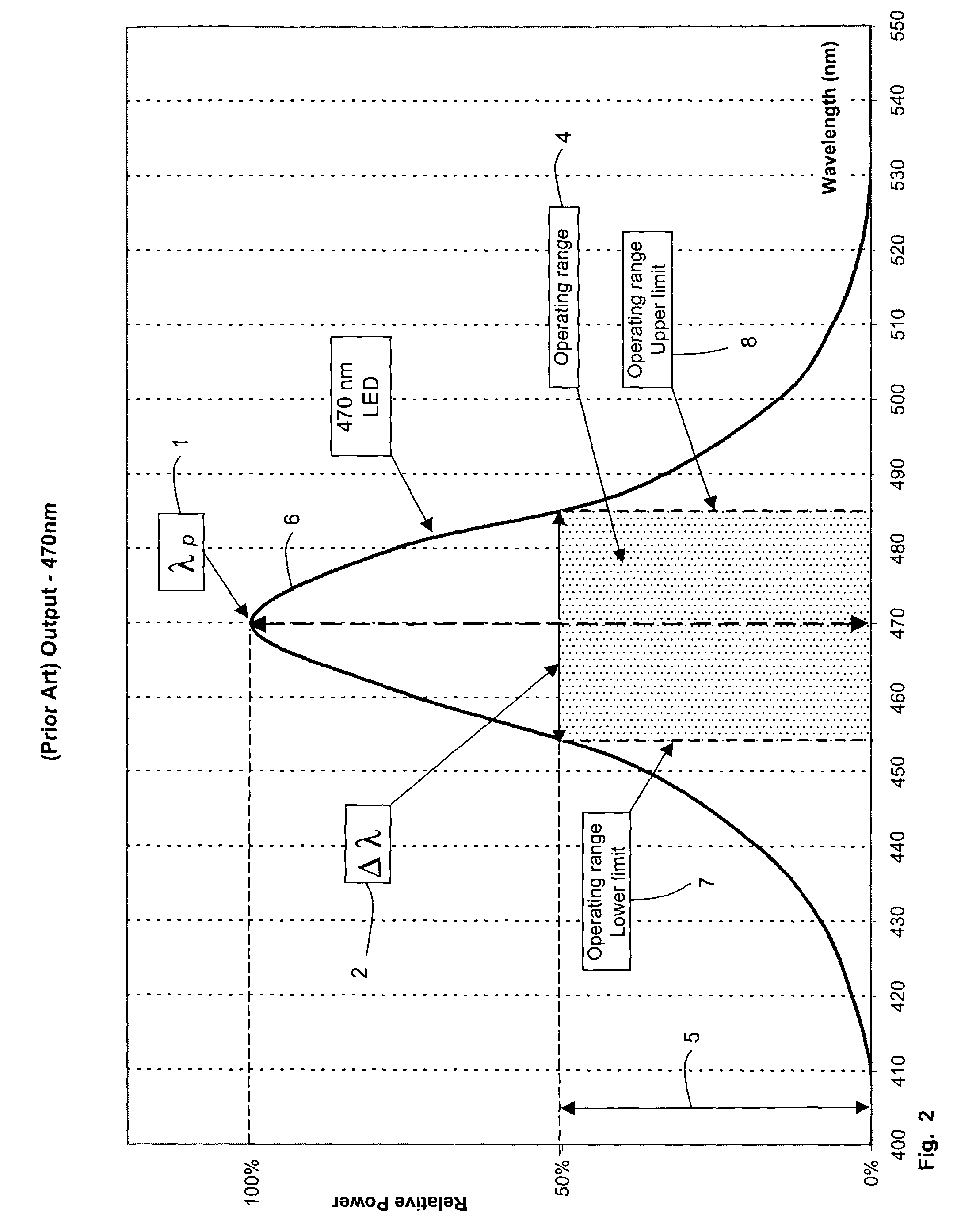
[0022]FIG. 1 illustrates a typical spectral line for a light source. Light energy concentrates near a peak (central) wavelength 1 (λp,), where a relative light power reaches a maximum relative value 3 of 1.0 at the peak wavelength 1. Here, power may be measured, for example, as an electrical output from a photodetector that is indicative of the light intensity.

[0023]The further a wavelength deviates from the peak wavelength, λp, the lower its light power amplitude. An important characteristic of this spectral line is i...


PUM


Abstract

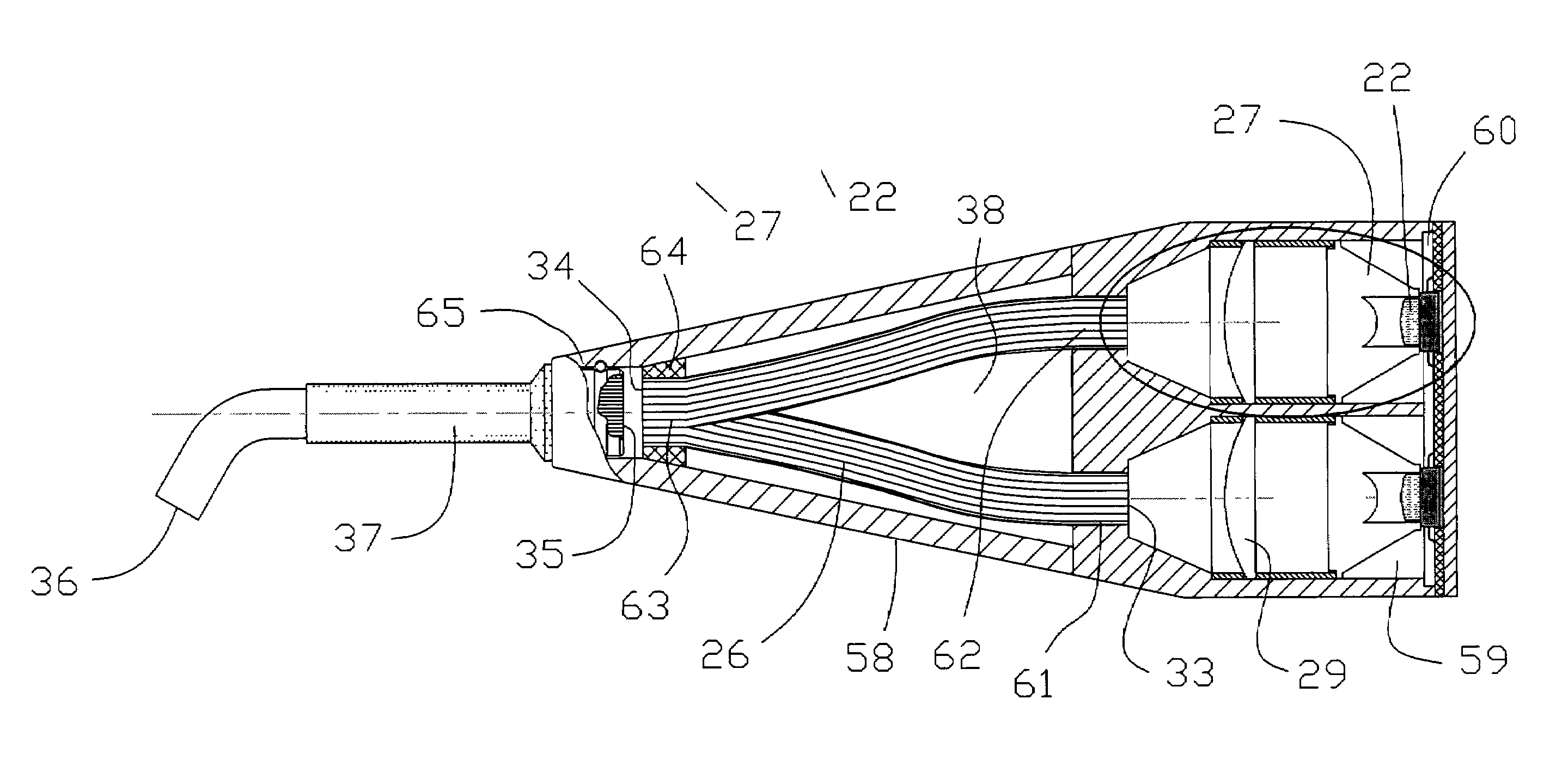
A light for a curing instrument includes a plurality of light sources, each producing an incident light beam. The incident light beams are combined to produce a single output beam, which exhibits a broader spectral width than any of the incident light beams. In one embodiment of the invention, the output beam exhibits an intensity over a spectral range defined by a first characteristic wavelength of a first of the plurality of light sources and a second characteristic wavelength of a second of the plurality of lights sources such that the intensity varies by no more than 25 percent over the range. In another embodiment of the invention including a one or more blue LED light sources among the plurality of light sources, at least one white LED is included in the plurality of light sources in order to generate an output light beam having a component portion that is characterized as green. In a third embodiment of the invention, a plurality of fiber optic bundles receive the incident light beams, and are arranged at a transmitting end so that individual fibers from the plurality of bundles are randomly combined to form a single output surface for transmitting the output beam.

Description

FIELD OF THE INVENTION[0001]The present invention relates to a light used for curing light-activated compound materials. In particular, the present invention relates to a curing light comprising two or more light sources whose outputs are integrally combined to produce a light spectrum suitable for curing a variety of light-activated compounds.BACKGROUND OF THE INVENTION[0002]Light-activated compounds are well known and used in a variety of commercial applications. For example, such compounds are widely used in a variety of dental procedures including restoration work and teeth filling after root canals and other procedures requiring drilling. Several well-known dental compounds have been sold, for example, under the trade names of BRILLIANT LINE, Z-100, TPH, CHARISMA and HERCULITE & BRODIGY.[0003]Dental compounds typically comprise liquid and powder components mixed together to form a paste. Curing of the compound requires the liquid component to evaporate, causing the composite to...

Claims


Application Information

Patent Timeline
Patent Type & Authority Patents(United States)
IPC IPC(8): A61C1/00A61C13/15A61C5/04A61N5/06
CPCA61C19/004A61N2005/0652
Inventor GOFMAN, IGOR Y.COLOMBO, JOSEPH G.
Owner COLTENE WHALEDENT INC
Why Eureka
Try Eureka