Injector system including a powered loading device for connecting a syringe to an injector

a technology of injectors and syringes, which is applied in the field of injectors and injector systems, can solve the problems of difficult access for operators to the injector to load a syringe, insufficient dexterity and strength, and insufficient safety of the injector head, so as to simplify the process of loading a front-loading syringe and free valuable operator tim

Inactive Publication Date: 2006-04-18
BAYER HEALTHCARE LLC
View PDF195 Cites 52 Cited by
  • Summary
  • Abstract
  • Description
  • Claims
  • Application Information

AI Technical Summary

Benefits of technology

[0010]The present invention provides improved injectors, injector systems, syringes and methods in which the syringe is loaded upon and / or unloaded from the injector in a powered or manual manner. The loading / connecting features of the present invention greatly simplify the process of loading a front-loading syringe onto an injector and frees valuable operator time to accomplish other tasks.
[0011]The powered loading features of the present invention also provide greater confidence of proper and secure engagement of the syringe to the injector and / or the syringe plunger to the injector drive member. Moreover, because the loading procedure is powered, tighter tolerances can be designed into the mounting and retaining mechanisms of the present invention than with previous front-loading systems in which tolerances were limited or loosened to facilitate manual loading. The tighter tolerances of the present invention substantially reduce or eliminate play or movement of the syringe after connection thereof to the injector, thereby facilitating more accurate control of the injector.
[0015]In several embodiments, the powered loader of the present invention moves one or more components of the retainer to engage the mounting member and to bring the mounting member and the retainer into secure connection, thereby securely connecting the syringe to the injector. For example, the mounting member may include threading and the retainer may include a cooperating threaded member. The powered loader may rotate the threaded member of the retainer relative to the threading on the syringe to engage the threading on the syringe and securely connect the syringe to the injector.
[0018]The syringe (or an adapter that is attached to the rear of the syringe as described above) may include a generally annular flange preferably positioned forward of the mounting flange(s) that forms a sealing engagement with a forward surface of the retainer to assist in creating a secure engagement of the syringe to the injector and to assist in preventing leakage of fluids into the injector.
[0020]The drive member may, for example, be automatically advanced forward upon loading of the syringe on the injector to connect the drive member to the plunger. Whether the drive member is connected to the plunger automatically or by manual control, the injector preferably controls the motion of the drive member based upon syringe information encoded upon the syringe. For example, if the injector determines that the syringe is empty from the syringe information encoded upon the syringe, the injector preferably causes the drive member to advance the plunger forward to expel air from the syringe in preparation for loading the syringe with fluid. However, if the injector determines that the syringe is prefilled from the syringe information encoded upon the syringe, the injector preferably stops forward advancement of the drive member upon connection of the drive member with the plunger to prevent undesirable expelling of injection fluid. Controlling the drive member, for example, to perform certain preinjection procedures in a manner that depends upon the type of syringe loaded upon the injector can save valuable user time and helps standardize injection procedures.

Problems solved by technology

These steps can require substantial time, dexterity and strength as a result of, for example, alignment requirements, awkward and complex motions and close design tolerances.
In many cases the injector may also be positioned so that it is difficult for the operator to access the injector to load a syringe thereon.
Moreover, injector heads are typically not securely anchored and can move during syringe loading, further complicating loading of a syringe thereon.

Method used


Image

  • Injector system including a powered loading device for connecting a syringe to an injector
  • Injector system including a powered loading device for connecting a syringe to an injector
  • Injector system including a powered loading device for connecting a syringe to an injector

Examples


Embodiment Construction

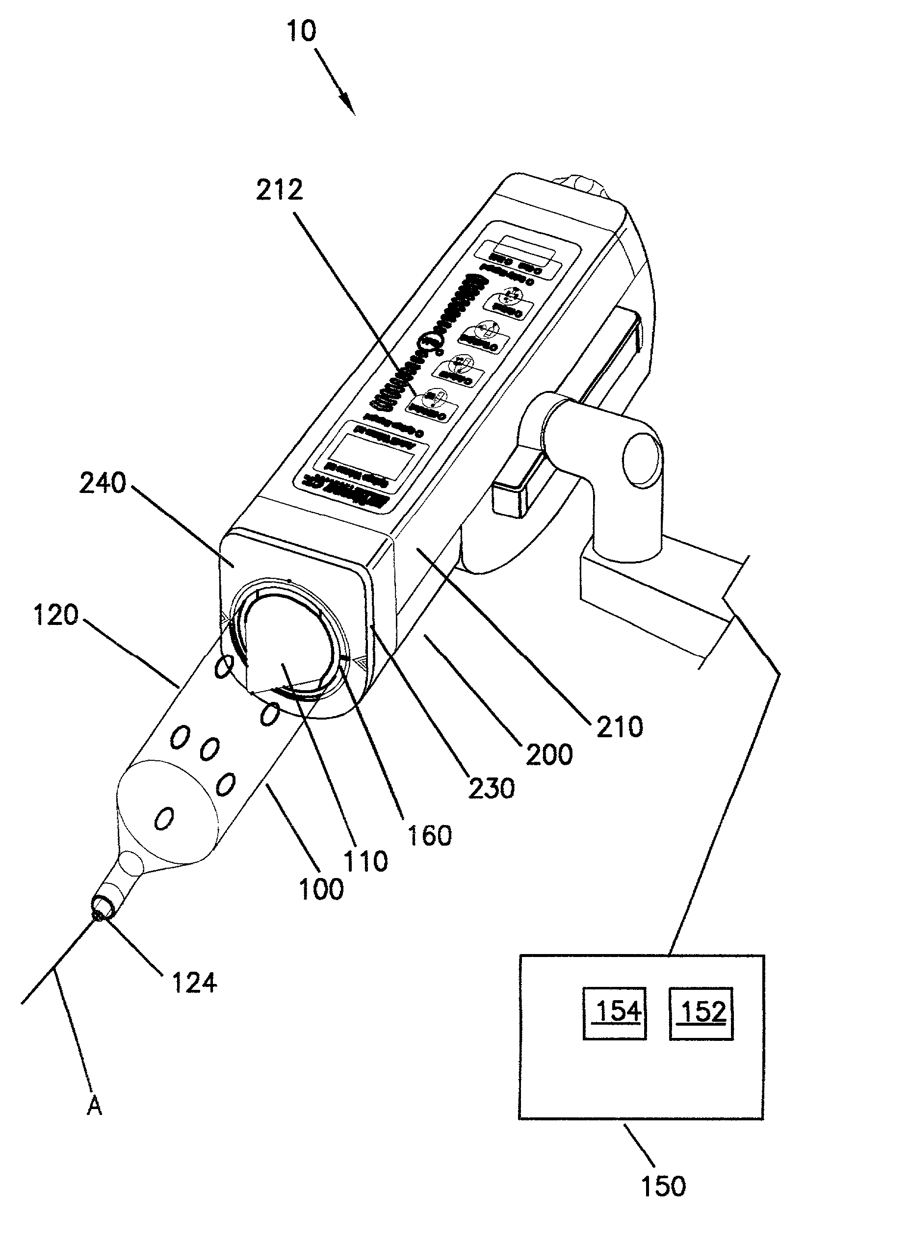
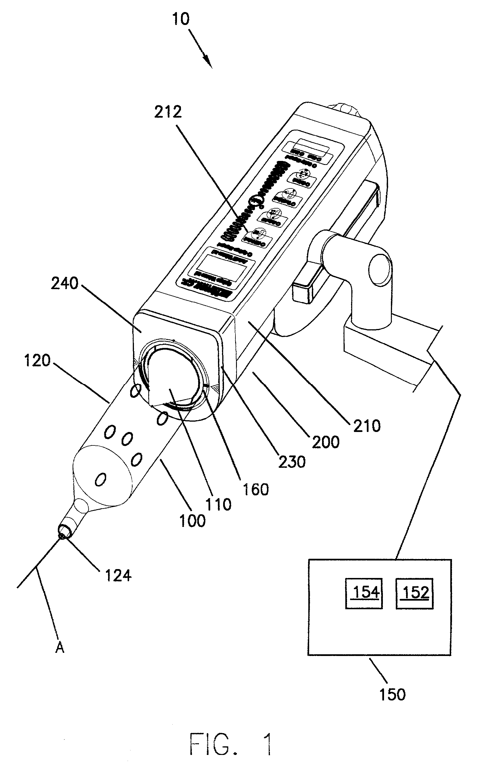
[0039]An embodiment of a front-loading injector system 10 of the present invention is illustrated in FIGS. 1 through 4D. Injector system 10 includes a syringe 100 and an injector 200. Injector housing 210 of injector 200 preferably includes a reciprocating piston 220 (see, for example, FIGS. 4A and 4C) therein which cooperates with a syringe plunger 110 disposed within an elongated cylindrical body 120 of syringe 100 to inject an injection fluid (for example, a liquid contrast medium) from the interior of syringe 100 into a patient. Piston 220 is preferably extendible and retractable via a powered means as known in the art (not shown) that is preferably contained within injection housing 210 and includes, for example, a motor or hydraulic system, including appropriate gearing (not shown). As also known in the art, injector 200 also preferably includes a motor controller for controlling operation of a motor and thereby controlling operation of piston 220. The operation of injector 20...


PUM


Abstract

An injector for injecting a fluid from a syringe, which includes an elongated body, a mounting member positioned on a rear portion of the body, and a plunger moveably positioned within the body of the syringe, includes a housing having a front wall and a retainer on the front wall. The retainer is adapted to cooperate with the mounting member to releasably retain the syringe on the front wall. The retainer includes a powered loader adapted to bring the mounting member and the retainer into secure engagement to securely connect the syringe to the injector. The injector further includes a powered drive member in the housing. The drive member is adapted to engage the plunger and control the movement of the plunger.

Description

CROSS-REFERENCE TO RELATED APPLICATION[0001]This application is a divisional of application Ser. No. 09 / 448,835, filed on Nov. 24, 1999 now U.S. Pat. No. 6,958,053, the contents of which are hereby incorporated by reference.BACKGROUND OF THE INVENTION[0002]The present invention relates to injectors and injector systems, and, more particularly, to injectors and injector systems in which a syringe is connected to or loaded upon the injector in a powered or manual manner.[0003]A number of injector-actuated syringes and powered injectors for use in medical procedures such as angiography, computed tomography and NMR / MRI have been developed. For example, U.S. Pat. No. 4,006,736 discloses an apparatus for injecting fluid into the vascular system of a human being or an animal. Likewise, U.S. Pat. No. 4,677,980 discloses an angiographic injector and syringe wherein the drive member of the injector can be connected to, or disconnected from, the syringe plunger at any point along the travel pa...

Claims


Application Information

Patent Timeline
Patent Type & Authority Patents(United States)
IPC IPC(8): A61M37/00A61M5/145
CPCA61M5/14546A61M5/14566Y10S128/01A61M2205/6018Y10S128/12A61M5/1458
Inventor REILLY, DAVID M.
Owner BAYER HEALTHCARE LLC
Why Eureka
Try Eureka