Variable reluctance resolver

a resolver and variable reluctance technology, applied in the direction of magnetic circuit rotating parts, magnetic circuit shapes/forms/construction, instruments, etc., can solve the problems of harmonic effect, practical application problems, and conventional methods that cannot be said to properly cancel harmonic components, etc., to achieve the effect of improving output properties

Active Publication Date: 2006-04-18
MINEBEAMITSUMI INC
View PDF17 Cites 25 Cited by
  • Summary
  • Abstract
  • Description
  • Claims
  • Application Information

AI Technical Summary

Benefits of technology

[0046]As the shaft angle multiplier becomes greater than 1× such as 2×, 4×, etc. as the number of poles increases, the angular range in which the rotor exhibits a sinusoidally varying property in relation to the gap permeance decreases. As the angular range decreases in this manner, the angular range of a single salient pole similarly decreases. As a result, the shape of the outer periphery of a salient pole can be made to closely match an arc of radius r. However, the center of the arc and the center of the rotor deviate from one another. The present inventors discovered that when an arc of a radius r optimally matched to the outer peripheral shape of each salient pole is used as a reference, and the distance between the center of the arc and the center of the rotor is set as an offset distance, the shape of the rotor can be designed in such a manner that the gap permeance exhibits the sinusoidally varying property. It was confirmed that even when the above design is applied to a VR resolver having a small number of salient poles, the gap permeance vary sinusoidally with high accuracy.
[0055]The gap between the stator and the rotor is found by a simulation based on Equation 5, so the gap permeance of the gap can be made to approach extremely close to properties which vary according to a sine function of the rotational angle, and output properties are improved.

Problems solved by technology

In light of these circumstances, the conventional methods can not be said to properly cancel harmonic components other than a first order component, and typically a third order harmonic error component, contained in the output signal.
Above-described example (3) of the background art forms the shape of the salient poles in accordance with above-described Equation 3, but the effect of harmonics still remains, and problems remain with respect to its practical application.

Method used


Image

  • Variable reluctance resolver
  • Variable reluctance resolver
  • Variable reluctance resolver

Examples


Embodiment Construction

[0059]An embodiment of the present invention will be described while referring to the accompany drawings.

[0060]A manufacturing method for a rotor in which a gap between the rotor and a stator is such that the difference between a measured value and a theoretical value approaches extremely close to zero and a rotor shape formed using this method will be described.

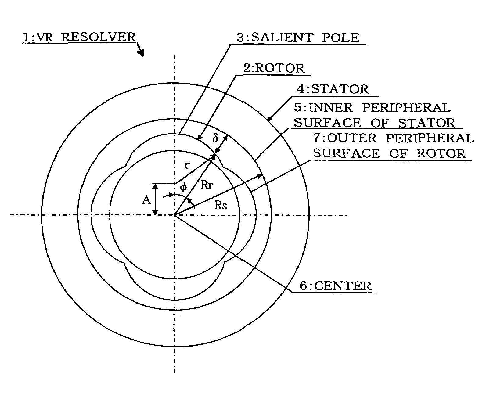
[0061]FIG. 1 shows an embodiment of a VR resolver 1 according to the present invention. It shows an example in which the shape of a magnetic rotor is determined by the above-described Equation 4, and in which the value of the gap δ between the rotor 2 and the stator 4, which determines the shape for the rotor 2, is determined by the above-described Equation 5. FIG. 1 shows the case in which the shaft angle multiplier N=4, i.e., the case in which the rotor 2 has four abutting salient poles 3 protruding from and evenly spaced around the periphery of a central circular portion.

[0062]In FIG. 1, δ is the gap measured in the radia...


PUM


Abstract

A variable reluctance resolver has a rotor which includes a noncircular core and which is rotatably supported inside a stator with a gap therebetween. The shape of the rotor is such that the gap permeance, which is based on the gap, varies according to a sine function of the rotational angle. Each of the salient poles of the rotor has an outer periphery comprising an arc of radius r centered on a point which is offset from the center of the rotor by a prescribed offset distance. The outer periphery of each salient pole does not extend to the inner periphery of the stator.

Description

BACKGROUND OF THE INVENTION[0001]1. Field of the Invention[0002]The present invention relates to a variable reluctance (VR) resolver, and in particular to a VR resolver which has a rotor which is shaped such that the gap permeance varies according to the sine of the rotational angle, which is expressed by the mechanical angle φ or the electrical angle θ corrected by a shaft angle multiplier (shaft angle multiplication factor).[0003]2. Related Art[0004]In the past, the shape of a rotor in a VR resolver was formed as described below in (1)–(3).[0005](1) In the case of a VR resolver whose rotor has no winding and which utilizes variations in reluctance at a gap, when the rotor is shaped to have a property such that the gap permeance varies in accordance with the sine of the rotational angle (referred to below as a “sinusoidally varying property”), the rotor has a simple structure of an iron core without windings, and a sinusoidal voltage with a period corresponding to the shape of the ...

Claims


Application Information

Patent Timeline
Patent Type & Authority Patents(United States)
IPC IPC(8): H02K17/42G01D5/245H02K24/00
CPCH02K24/00
Inventor KOBAYASHI, MASAHIROKUJIRAI, HIROYUKIKOYAMA, TAKANOBUAOKI, NAO
Owner MINEBEAMITSUMI INC
Why Eureka
Try Eureka