Multi-polarized feeds for dish antennas

a technology of dish reflector antenna and feed element, which is applied in the direction of antenna details, polarised antenna unit combinations, antennas, etc., can solve the problems of low efficiency, low efficiency, and inability to achieve desired goals,

Inactive Publication Date: 2006-04-18
MP ANTENNA
View PDF12 Cites 12 Cited by
  • Summary
  • Abstract
  • Description
  • Claims
  • Application Information

AI Technical Summary

Benefits of technology

[0019]These and other advantages and novel features of the present invention, as well as details of an i

Problems solved by technology

A focus on gain as well as circuitry solutions have proven to have significant limitations.
Unresolved, non-optimized (leading edge) technologies have often given way to “bleeding edge” attempted resolutions.
Unfortunately, all have fallen short of desirable goals, and some ventures/companies have even gone out of business as a result.
However, with topographical changes (hills & valleys) and object obstructions (e.g., natural such as trees, and man-made such as buildings/walls) and with the resultant reflections, diffractions, refractions and scattering, maximum signal received may well be off-axis (non-direct path) and multi-path (partial) cancellation of signals results in null/weaker spots.
Also, some antennas may benefit from having gain at one elevation angle (‘capturing’

Method used


Image

  • Multi-polarized feeds for dish antennas
  • Multi-polarized feeds for dish antennas
  • Multi-polarized feeds for dish antennas

Examples


first embodiment

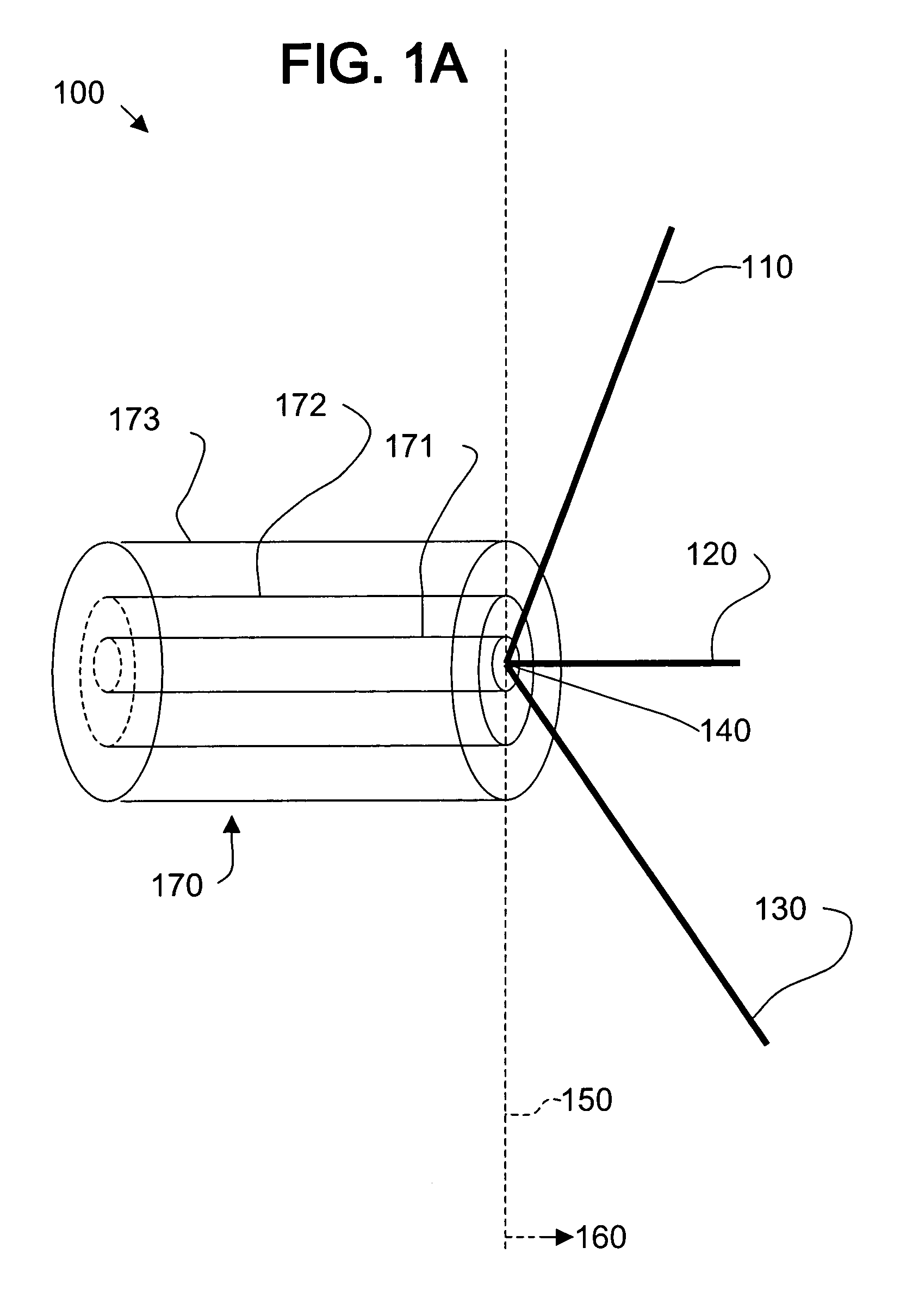
[0030]FIG. 1A illustrates a multi-polarized forward feed element 100, in accordance with various aspects of the present invention. The multi-polarized feed element 100 comprises a first radiative member 110, a second radiative member 120, and a third radiative member 130. The three radiative members 110, 120, and 130 of the feed element 100 are electrically connected together at an apex point 140 such that the three radiative members 110, 120, and 130 are each disposed outwardly away from the apex point 140 at an acute angle of between 1 degree and 89 degrees relative to an imaginary plane 150 intersecting the apex point 140. The radiative members 110, 120, and 130 are all located to a first side 160 of the imaginary plane 150.

[0031]When multiple radiative members (e.g., three) are positioned over a ground plane and properly spaced, many more polarizations may be generated and / or received in many more different directions than for a single radiative member. Therefore, such a feed el...

second embodiment

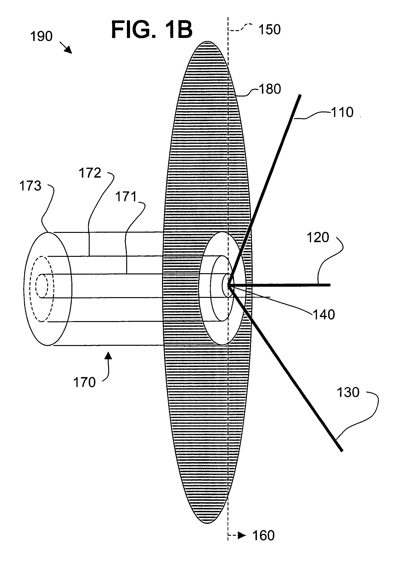
[0035]FIG. 1B illustrates a multi-polarized forward feed element 190, in accordance with various aspects of the present invention. The feed element 190 includes all of the elements of FIG. 1A and further includes a ground plane 180. In accordance with an embodiment of the present invention, the ground plane comprises a flat circular conductor having a radius of at least ¼ wavelength of a tuned radio frequency.

[0036]For example, the center conductor 171 may electrically connect to the apex 140 of the radiative members 110, 120, and 130 and the outer conductor 173 may electrically connect to the ground plane 180. The insulating dielectric region 172 electrically isolates the center conductor 140 (and therefore the radiative members 110, 120, and 130) from the outer conductor 173 (and therefore from the ground plane 180). The insulating dielectric region 172 may also serve to mechanically connect the radiative members 110, 120, and 130 to the ground plane 180, in accordance with an emb...

third embodiment

[0078]FIG. 6C illustrates a modified configuration 700 of a multi-polarized forward feed and dish configuration 600 shown in FIG. 6B, in accordance with various aspects of the present invention. The modified configuration 700 further angles the ground plane beam antennas 610 and 630 and corresponding dish reflectors 620 and 640 in a second plane (x-z plane). Such a configuration 700 may provide additional spatial diversity.


PUM


Abstract

A multi-polarized forward feed and dish configuration for transmitting and/or receiving radio frequency (RF) signals is disclosed. The configuration comprises a conductive reflector dish, having a focal point and a vertex point, and a multi-polarized forward feed element positioned substantially at the focal point. The forward feed element comprises at least two radiative members each having a first end and a second end. The second ends of the radiative members are electrically connected at an apex point and are each disposed outwardly away from the apex point toward the vertex point at an acute angle relative to an imaginary plane intersecting the apex point.

Description

CROSS-REFERENCE TO RELATED APPLICATIONS / INCORPORATION BY REFERENCE[0001]This application is a continuation-in-part (C-I-P) of patent application Ser. No. 10 / 294,420 filed on Nov. 14, 2002, now U.S. Pat. No. 6,806,841 isued Oct. 19, 2004, which is incorporated herein by reference in its entirety.[0002]U.S. application Ser. No. 10 / 787,031 entitled “Apparatus and Method for a Multi-Polarized Antenna” and filed on the same day as the application herein, is incorporated herein by reference in its entirety.[0003]U.S. application Ser. No. 10 / 787,025 entitled “Apparatus and Method for a Multi-Polarized Ground Plane Beam Antenna” and filed on the same day as the application herein, is incorporated herein by reference in its entirety.[0004]U.S. Pat. No. 6,496,152 issued on Dec. 17, 2002 is incorporated herein by reference in its entirety.TECHNICAL FIELD[0005]Certain embodiments of the present invention relate to feed elements for dish reflector antennas used in wireless communications. More p...

Claims


Application Information

Patent Timeline
IPC IPC(8): H01Q19/12H01Q1/24H01Q9/44H01Q13/00H01Q19/00H01Q19/10
CPCH01Q1/242H01Q1/3275H01Q21/24H01Q9/46H01Q19/10H01Q9/44
Inventor NILSSON, JACK
Owner MP ANTENNA
Why Eureka
Try Eureka