Liquid crystal display device, substrate assembly for liquid crystal display device, and electronic apparatus having a substantially equivalent display quality in both transmissive and reflective display modes
a liquid crystal display and substrate technology, applied in the direction of photomechanical treatment originals, radioactive control devices, instruments, etc., can solve the problems of insufficient visibility, difficult to view the display in a dark place, and difficult to obtain fine color display in transmissive display modes, etc., to achieve superior visibility
- Summary
- Abstract
- Description
- Claims
- Application Information
AI Technical Summary
Benefits of technology
Problems solved by technology
Method used
Image
Examples
first embodiment
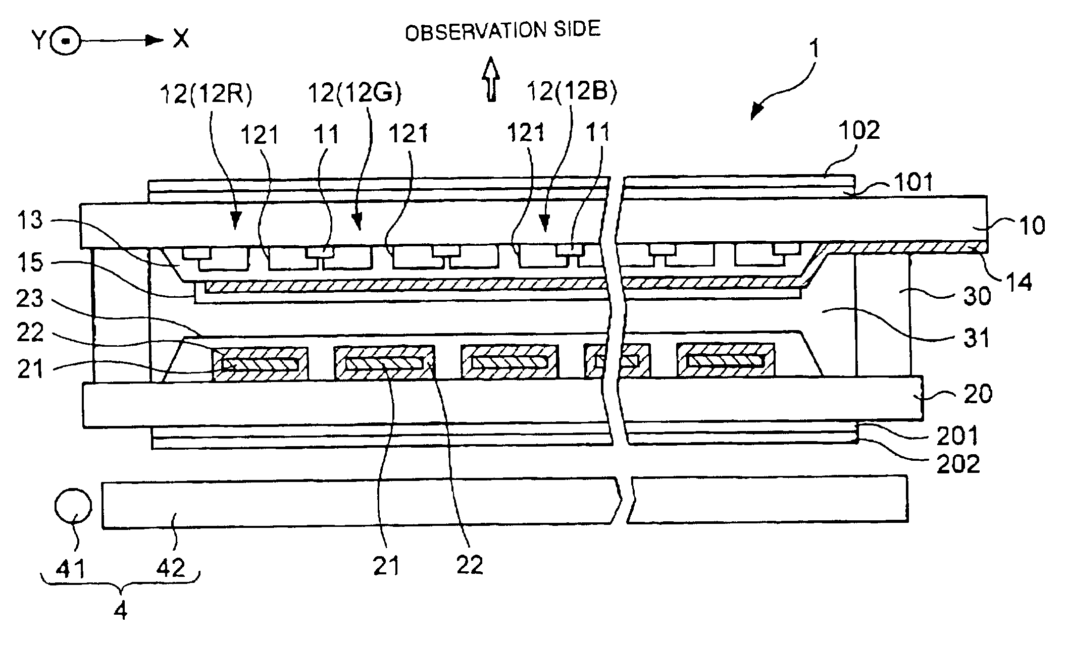
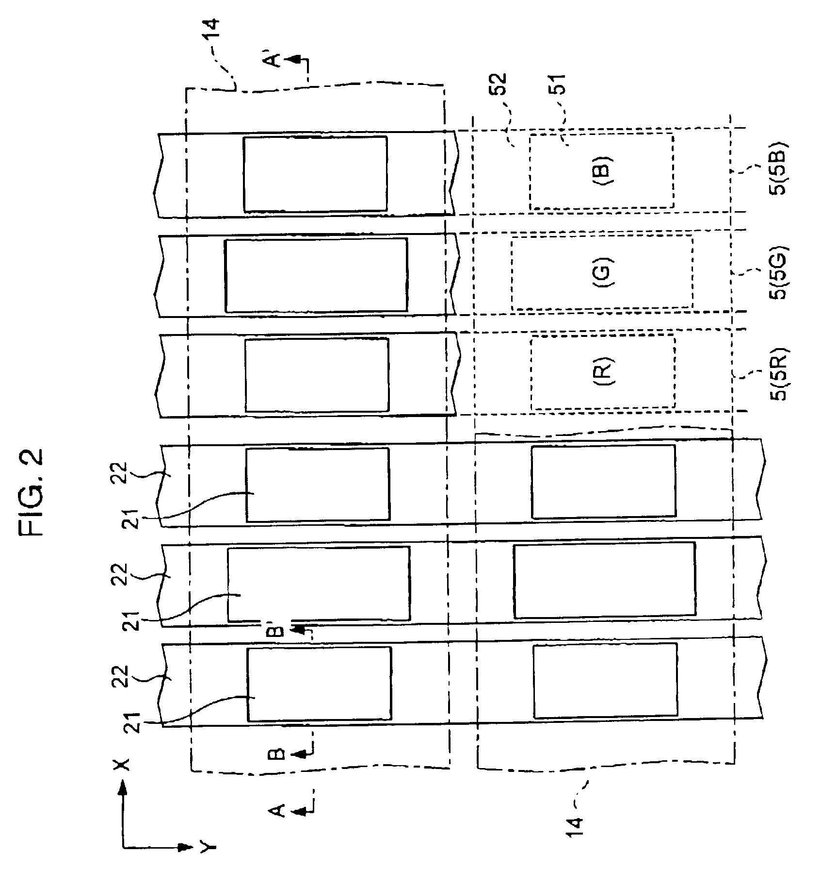
[0058]First, referring to FIG. 1, an embodiment in which the present invention is applied to a passive matrix type transflective liquid crystal panel will be described. As shown in the figure, a liquid crystal display device comprises a liquid crystal panel 1 and a backlight unit 4. The liquid crystal panel 1 has the structure in which a first substrate (upper substrate) 10 and a second substrate (lower substrate) 20 opposing thereto are bonded to each other with a sealing material 30 provided therebetween, and liquid crystal 31 such as a TN (twisted nematic) or a STN (super twisted nematic) type is enclosed in a region surrounded by the two substrates described above and the sealing material 30. The backlight unit 4 is disposed at the second substrate 20 side of the liquid crystal panel 1. Hereinafter, as shown in FIG. 1, a side opposite to the backlight unit 4 with respect to the liquid crystal panel 4 is called “observation side”. That is, the “observation side” means a side at w...
second embodiment
[0086]Next, a liquid crystal panel according to a second embodiment of the present invention will be described.
[0087]In the first embodiment, the structure in which the shading layer 11, the color filters 12, and the overcoat layer 13 are provided on the first substrate 10 located at the observation side is described by way of example. In this embodiment, the structure in which the elements described above are provided on the second substrate 20 is formed.
[0088]FIG. 8 is a cross-sectional view showing the structure of the liquid crystal panel of this embodiment, and FIG. 9 includes a plan view and a cross-sectional view showing the positional relationship between dots, color filters and reflective layers in the liquid crystal panel. The same reference numerals of the constituent elements of the liquid crystal panel 1 according to the first embodiment designate the equivalent constituent elements shown in FIGS. 8 and 9.
[0089]As shown in FIGS. 8 and 9, on the second substrate 20, a pl...
first modified embodiment
[0095]In the first and the second embodiments described above, in order to compensate for the difference in transmittance properties among the color filters 12 corresponding to different colors, the areas of the reflective layer 21 and the opening portion 121 of the color filter 12G corresponding to the green dot 5G are made different from those corresponding to the red dot 5R and blue dot 5B, and, in addition, the areas of those described above corresponding to the red dot, green dot, and blue dot may be made different from each other. In addition, in the embodiments described above, the areas of the reflective layers 21 and the areas of the opening portions 121 of the color filters 12 corresponding to the individual color dots are made different from each other in accordance with the transmittance properties of the color filters 12, and in addition, the areas described above corresponding to the individual color dots may be made different from each other in accordance with the spe...
PUM
| Property | Measurement | Unit |
|---|---|---|
| distance | aaaaa | aaaaa |
| wavelength | aaaaa | aaaaa |
| wavelength | aaaaa | aaaaa |
Abstract
Description
Claims
Application Information
 - R&D
- Intellectual Property
- Life Sciences
- Materials
- Tech Scout
- Unparalleled Data Quality
- Higher Quality Content
- 60% Fewer Hallucinations
Browse by: Latest US Patents, China's latest patents, Technical Efficacy Thesaurus, Application Domain, Technology Topic, Popular Technical Reports.
© 2025 PatSnap. All rights reserved.Legal|Privacy policy|Modern Slavery Act Transparency Statement|Sitemap|About US| Contact US: help@patsnap.com


