Heat-dissipating module

a heat dissipation module and module technology, applied in the direction of machines/engines, stators, liquid fuel engines, etc., can solve the problems of low heat dissipation efficiency, achieve the effect of increasing the overall air inlet amount and the overall air outlet amount, and improving the overall heat dissipation efficiency

Inactive Publication Date: 2006-04-18
SUNONWEALTH ELECTRIC MACHINE IND
View PDF13 Cites 66 Cited by
  • Summary
  • Abstract
  • Description
  • Claims
  • Application Information

AI Technical Summary

Benefits of technology

[0006]An object of the present invention is to provide a heat-dissipating module for increasing the overall air inlet amount and the overall air outlet amount, thereby improving the overall heat-dissipating efficiency.
[0007]Another object of the present invention is to provide a heat-dissipating module for avoiding non-uniform air density distribution in the heat-dissipating module and lowering the wind noise generated during operation of the heat-dissipating module when the first fan unit operates abnormally. The overall heat-dissipating efficiency is thus improved.SUMMARY OF THE INVENTION
[0009]The air inlet amount and the air outlet amount of the second fan unit are increased when the first fan unit operates normally. In a case that the impeller of the first fan unit operates abnormally and thus results in a low air-blowing efficiency, the impeller of the second fan unit compensates the shortage of air inlet amount resulting in abnormal operation of the impeller of the first fan unit by introducing air into the heat-dissipating module via the side air inlet. The air density distribution is uniform, and the wind noise during operation is lowered.

Problems solved by technology

In a case that the impeller of the first fan unit operates abnormally and thus results in a low air-blowing efficiency, the impeller of the second fan unit compensates the shortage of air inlet amount resulting in abnormal operation of the impeller of the first fan unit by introducing air into the heat-dissipating module via the side air inlet.

Method used


Image

  • Heat-dissipating module
  • Heat-dissipating module
  • Heat-dissipating module

Examples


first embodiment

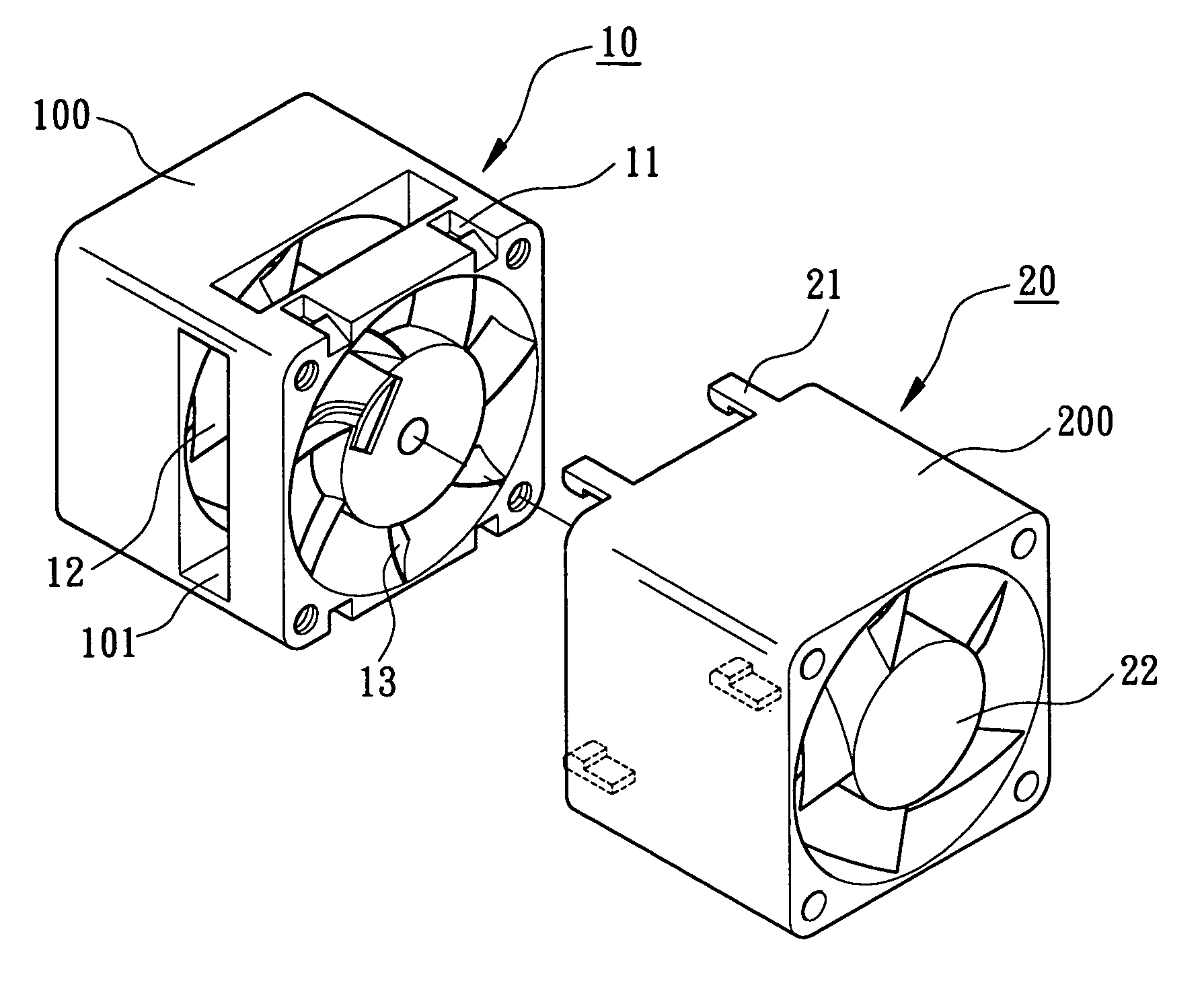
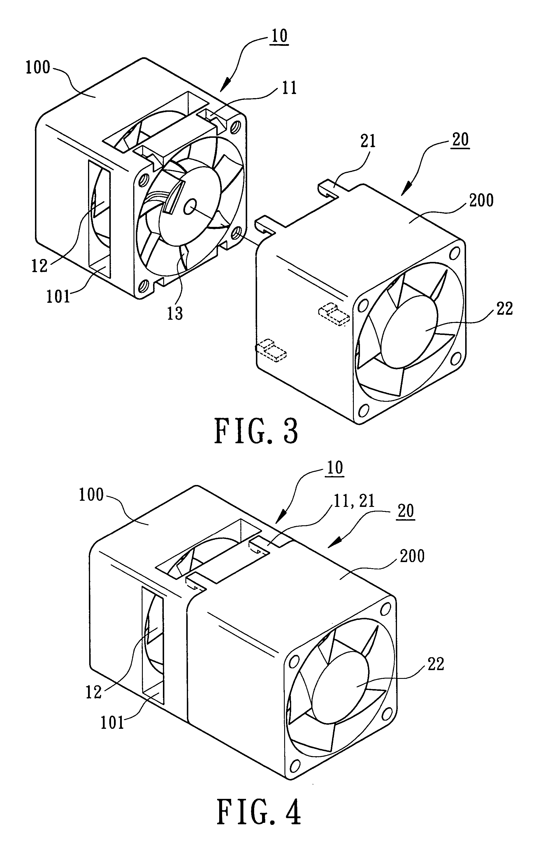
[0025]Referring to FIGS. 3 and 4, a heat-dissipating module in accordance with the present invention includes a first fan unit 10, a second fan unit 20, connecting means for connecting first fan unit 10 and the second fan unit 20, and at least one side air inlet 101. The first fan unit 10 is located on the air inlet side and includes a casing 100 in which an impeller 12 is received. The second fan unit 20 is located on the air outlet side and includes a casing 200 in which an impeller 22 is received.

[0026]In this embodiment, the connecting means includes a plurality of engaging grooves 11 defined in the casing 100 of the first fan unit 10 and a plurality of engaging tabs 21 extending from the casing 200 of the second fan unit 20 for engaging with the engaging groove 11 of the casing 100 of the first fan unit 10, thereby serially connecting the first fan unit 10 and the second fan unit 20.

[0027]In this embodiment, there are four side air inlets 101 respectively in the four sides of t...

second embodiment

[0030]FIGS. 5 and 6 illustrate the heat-dissipating module in accordance with the present invention, wherein at least one side air inlet 201 is defined in at least one of four side walls of the casing 200 of the second fan unit 20. In a preferred embodiment, there are four side air inlets 201 respectively in the four sides of the casing 200 of the second fan unit 20, and the side air inlets 201 are defined in the side walls of the casing 200 of the second fan unit 20 at a location adjacent to the air inlet side of the casing 200 of the second fan unit 20. Namely, the side air inlets 201 are adjacent to two mutually facing end faces of the first fan unit 10 and the second fan unit 20. Thus, the respective side air inlet 201 is close to the air inlet side of the impeller 22 of the second fan unit 20.

[0031]Thus, the amount of inlet air and the amount of the outlet air of the second fan unit 20 can be increased through provision of the side air inlets 201 when the first fan unit 10 oper...

third embodiment

[0032]FIG. 7 illustrates the heat-dissipating module in accordance with the present invention, wherein at least one side air inlet 101 is defined in at least one of four side walls of the casing 100 of the first fan unit 10 and at least one side air inlet 201 is defined in at least one of four side walls of the casing 200 of the second fan unit 20. The overall air-introducing area of the side air inlets 101 and 201 is relatively large and thus increases the air inlet amount sucked by the impeller 200 of the second fan unit 20 through the side air inlets 101 and 201. The number of the side air inlets 101 and 201 can be altered according to need.


PUM


Abstract

A heat-dissipating module includes a first fan unit and a second fan unit, which are serially connected together to provide an air inlet and an air outlet. Each of the first fan unit and the second fan unit includes a casing and an impeller. At least one side air inlet is defined in at least one of a plurality of sides of the casing of the first fan unit and a plurality of sides of the casing of the second fan unit. The air inlet amount and the air outlet amount of the second fan unit are increased by the side air inlet. The air density distribution is uniform, and the wind noise during operation is lowered.

Description

BACKGROUND OF THE INVENTION[0001]1. Field of the Invention[0002]The present invention relates to a heat-dissipating module. In particular, the present invention relates to a heat-dissipating module including a plurality of serially connected heat-dissipating fan units.[0003]2. Description of Related Art[0004]FIG. 1 is an exploded perspective view of a conventional heat-dissipating module. FIG. 2 is a perspective view of the conventional heat-dissipating module. The heat-dissipating module includes a first fan unit 10 and a second fan unit 20, which are serially connected together to provide an air inlet and an air outlet. The first fan unit 10 is located on the air inlet side, and the second fan unit 20 is located on the air outlet side. Generally, the casing 100 of the first fan unit 10 includes a plurality of engaging notches or grooves 11 and the casing 200 of the second fan unit 20 includes a plurality of engaging tabs 21 for engaging with the engaging grooves 11, thereby serial...

Claims


Application Information

Patent Timeline
Patent Type & Authority Patents(United States)
IPC IPC(8): H05K7/20F04D19/00F04D25/16F04D29/40
CPCF04D19/007H05K7/20172F04D25/166
Inventor HORNG, ALEXHONG, YIN-RONGHONG, CHING-SHENG
Owner SUNONWEALTH ELECTRIC MACHINE IND
Why Eureka
Try Eureka