Distributed monitoring and analysis system for network traffic

a network traffic and analysis system technology, applied in the field of network monitoring and analysis systems, can solve the problems of inaccurate measurement, mischaracterization of the actual contribution of the network to a given measurement, and the conventional monitoring and analysis system such as those noted above exhibits a number of significant problems, and achieves accurate measurement of jitter, loss, delay

Active Publication Date: 2006-04-18
AVAYA INC
View PDF11 Cites 50 Cited by
  • Summary
  • Abstract
  • Description
  • Claims
  • Application Information

AI Technical Summary

Benefits of technology

[0014]Advantageously, the invention allows accurate measurements of jitter, loss, delay and other QoS-re

Problems solved by technology

Conventional monitoring and analysis systems such as those noted above exhibit a number of significant problems.
One problem is that these conventional systems are often configured such that application-related effects can lead to mischaracterization of the actual contribution of the network to a given measurement.
For example, the actual transmit time for sending out test traffic over the network in the conventional systems may be significantly delayed relative to its recorded transmit time if the endpoint device used to send the test traffic becomes busy with other processing tasks, thereby rendering the resulting measurements inaccurate.
Another problem relates to clock synchronization.
Unfortunately, this approach is problematic in that cl

Method used


Image

  • Distributed monitoring and analysis system for network traffic
  • Distributed monitoring and analysis system for network traffic
  • Distributed monitoring and analysis system for network traffic

Examples


Embodiment Construction

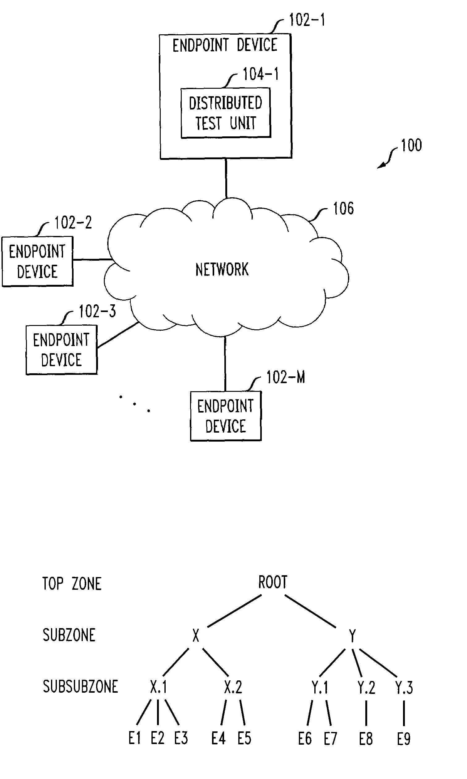
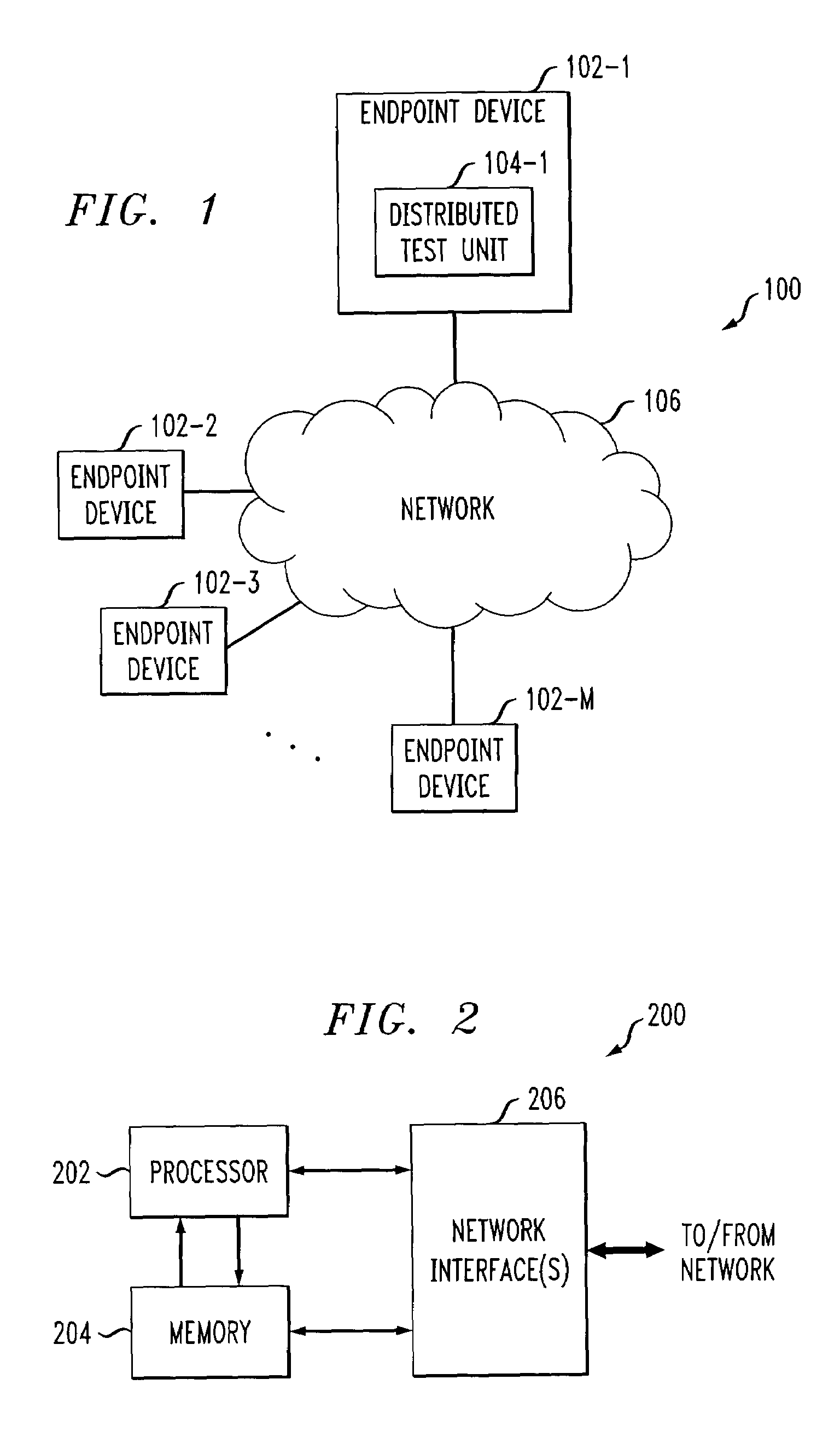
[0020]The invention will be illustrated below in conjunction with an exemplary communication system suitable for supporting Internet telephony applications. It should be understood, however, that the invention is not limited to use with any particular type of communication system or configuration of endpoint devices or other system elements. Those skilled in the art will recognize that the disclosed techniques may be used in any communication application in which it is desirable to provide improved monitoring and analysis of Internet protocol (IP) communications or other types of real-time or non-real-time network traffic in a network-based communication system.

[0021]Moreover, the invention, although particularly well-suited for use in monitoring and analysis of VoIP traffic, also provides significant advantages in multimedia traffic applications or other flow-based real-time applications in which it is desirable to understand end-to-end behavior attributable to a network.

[0022]The ...


PUM


Abstract

Techniques are disclosed for improved monitoring and analysis of VoIP communications, multimedia communications or other types of network traffic in a network-based communication system. In accordance with one aspect of the invention, endpoint devices of the network-based communication system are configurable so as to collectively implement a distributed monitoring and analysis system which does not require a centralized testing server or other centralized controller. Distributed test units associated with the endpoint devices may be utilized in implementing the distributed monitoring and analysis system, and are preferably configured to support a web-based user interface providing access to measurement data. The endpoint devices may be advantageously organized into a hierarchy comprising a plurality of zones, with each of the endpoint devices belonging to at least one zone. For each zone, one of the endpoint devices may be designated as a zone leader for controlling the periodic generation of communications between selected endpoint devices that belong to subzones of that zone in the hierarchy.

Description

[0001]A portion of the disclosure of this patent document contains material which is subject to copyright protection. The copyright owner has no objection to the facsimile reproduction by anyone of the patent document or the patent disclosure, as it appears in the Patent and Trademark Office patent file or records, but otherwise reserves all copyright rights whatsoever.RELATED APPLICATION(S)[0002]The present application is related to U.S. patent application Ser. No. 10 / 460,700, filed concurrently herewith in the name of inventors A. Adhikari et al. and entitled “Method and Apparatus for Determination of Network Topology,” the disclosure of which is incorporated by reference herein.FIELD OF THE INVENTION[0003]The invention relates generally to network monitoring and analysis systems, and more particularly to techniques for the monitoring and analysis of Voice over Internet Protocol (VoIP) communications, multimedia communications or other types of network traffic in a network-based c...

Claims


Application Information

Patent Timeline
IPC IPC(8): H04L12/56H04L12/24H04L12/26H04L12/66
CPCH04L43/12H04L43/0829H04L43/0835H04L43/0858H04L43/087H04L43/106H04L43/0864H04L12/66
Inventor ADHIKARI, AKSHAYBIANCO, SCOTT VINCENTDENBY, LORRAINEMALLOWS, COLIN L.MELOCHE, JEANRAO, BALAJISULLIVAN, SHANE M.VARDI, YEHUDA
Owner AVAYA INC
Why Eureka
Try Eureka