Method and apparatus for providing orthogonal spot beams, sectors, and picocells

a spot beam and orthogonal technology, applied in the field of communication, can solve the problems of affecting the performance of the communication system, and spreading of signals from other sectors, so as to improve capacity, reduce interference, and improve the effect of capacity

Inactive Publication Date: 2006-04-18
QUALCOMM INC
View PDF2 Cites 3 Cited by
  • Summary
  • Abstract
  • Description
  • Claims
  • Application Information

AI Technical Summary

Benefits of technology

[0013]It is an object of the present invention to provide orthogonal spot beams, sectors, and picocells. In the exemplary embodiment, the traffic channels in a transmission area are covered with Walsh sequences which are orthogonal to those of adjacent areas. In addition, the pilot for each transmission area is covered with pilot Walsh sequence which is derived from Walsh sequence zero. Orthogonal traffic channels and pilots minimize interference and improve capacity.
[0014]It is another object of the present invention to provide additional orthogonal pilot channels without reducing the number of orthogonal Walsh channels available for traffic and control channels. In accordance with the IS-95 standard, 64 Walsh sequences are available for covering 64 code channels. Walsh sequence zero is reserved for the pilot channel and the remaining 63 Walsh sequences can be used for other code channels, such as traffic channels and control channels. In the present invention, the additional pilot signals are generated using concatenated combinations of the all zeros and all ones sequences. All pilot signals are orthogonal t...

Problems solved by technology

Thus, when a remote station is in overlapping sector coverage areas and demodulating the signal from one sector, the signals from other sectors are spread and appear as wideband interference.
The n...

Method used


Image

  • Method and apparatus for providing orthogonal spot beams, sectors, and picocells
  • Method and apparatus for providing orthogonal spot beams, sectors, and picocells
  • Method and apparatus for providing orthogonal spot beams, sectors, and picocells

Examples


Embodiment Construction

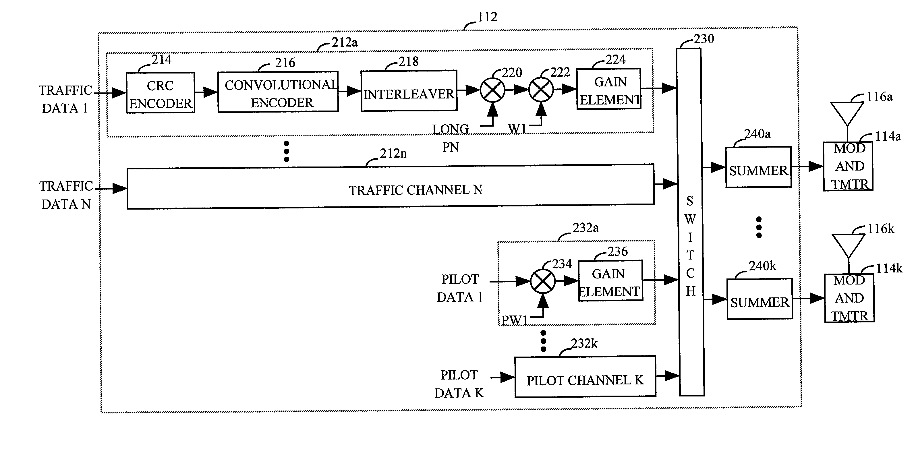
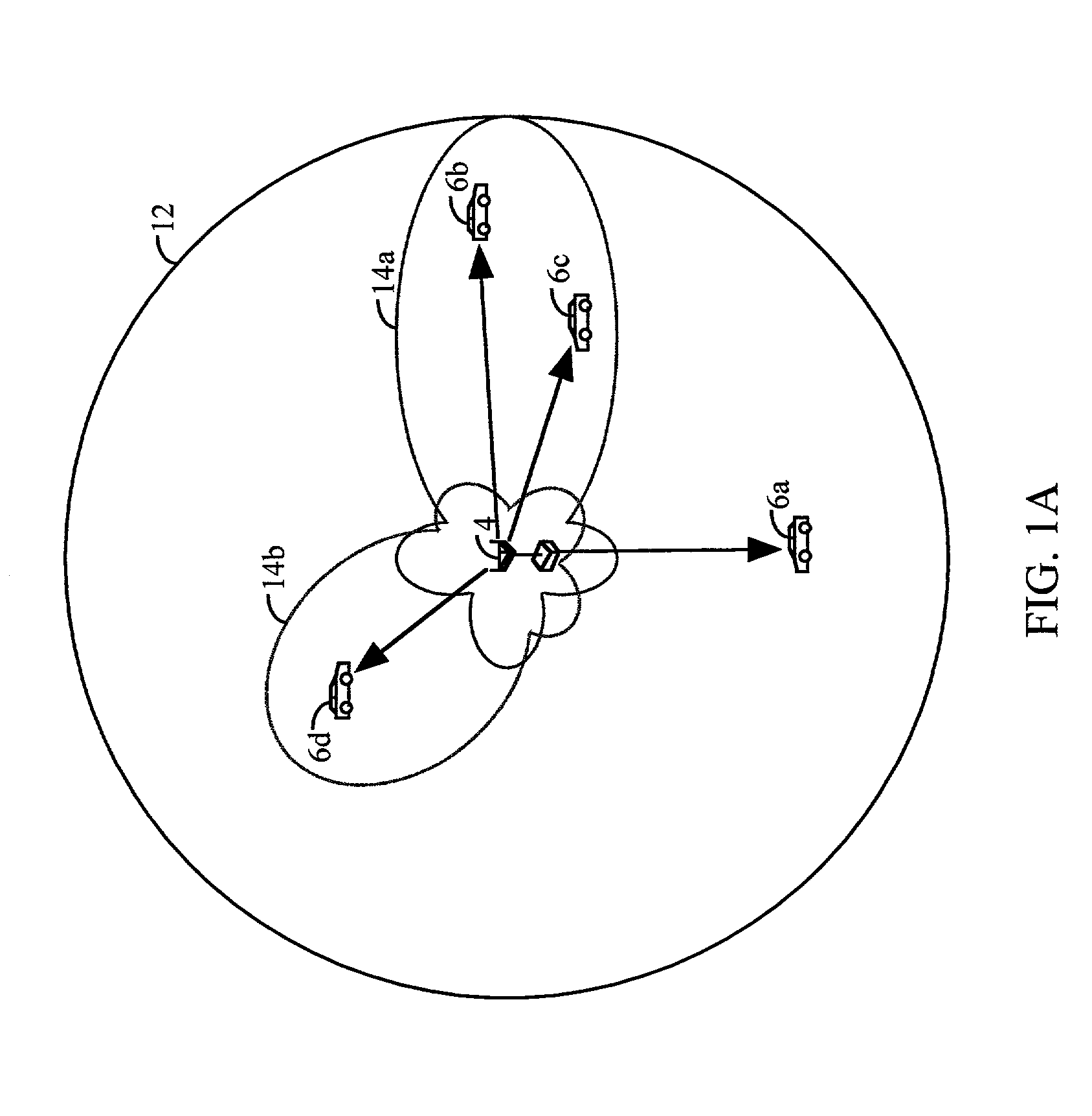
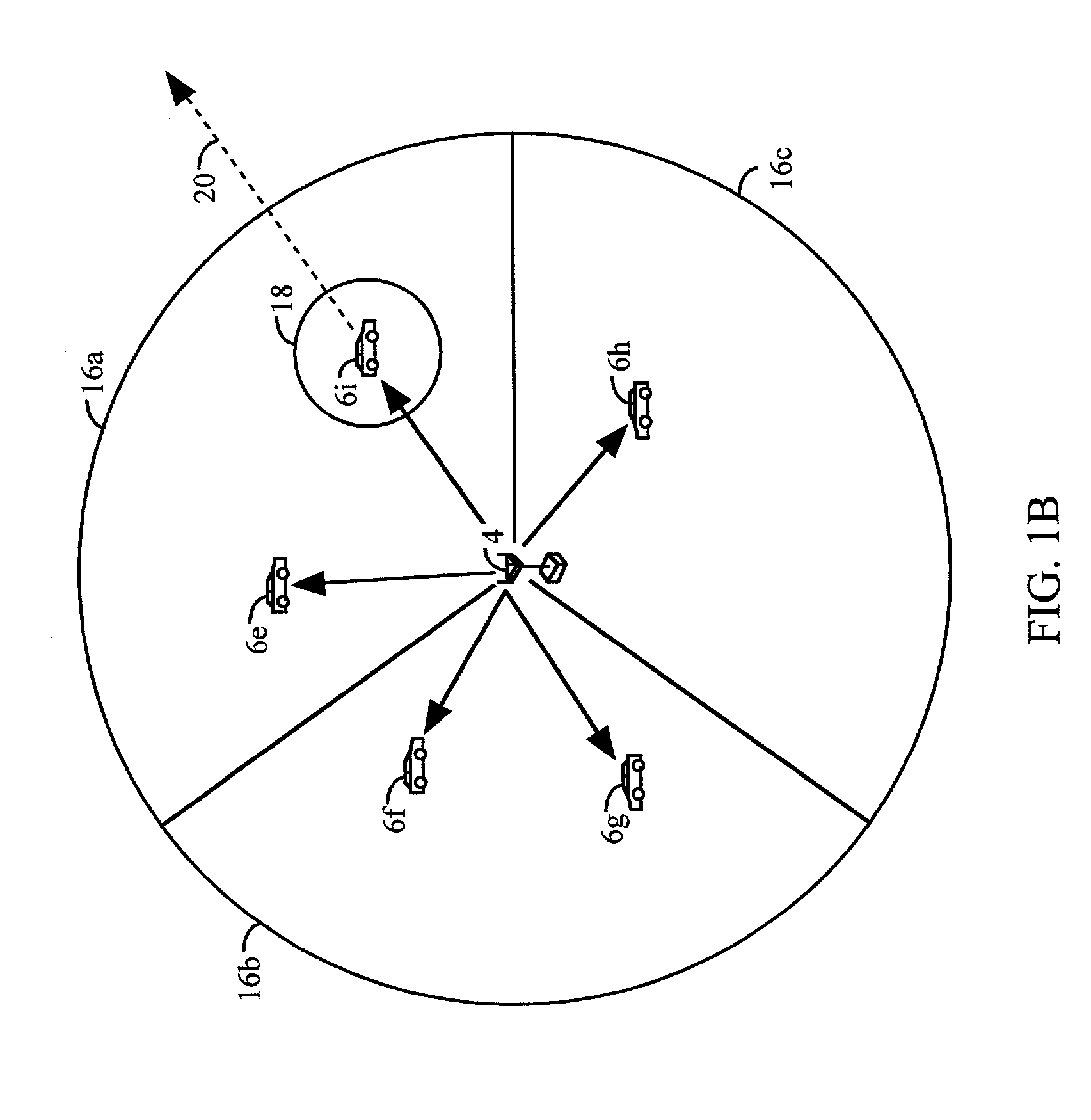
[0024]The present invention is a method and apparatus for providing orthogonal spot beams, sectors, and picocells. In accordance with the IS-95 standard, the forward link comprises 64 orthogonal code channels which are generated by covering each code channel with one of 64 unique Walsh sequences. In accordance with the IS-95 standard, Walsh sequence zero is reserved for the pilot signal. To increase capacity, the forward link transmission can comprise multiple transmissions. Each transmission can be directed to a particular area by the use of directive antennas. For example, a transmission can be directed at the entire area surrounding the base station (e.g., an omni-directional transmission), a sector of a cell, or a localized area within a sector or a cell using spot beams or picocells. Spot beams provide antenna gain, minimize interference, and increase capacity. In this specification, a particularized transmission comprises a transmission covering a cell, a sector, or a picocell...


PUM


Abstract

A method and apparatus for providing orthogonal spot beams (14a, 14b), sectors (16a, 16b), and picocells (18), by using orthogonal auxiliary pilots and different Walsh traffic channels in adjacent areas. According to the IS-95 standard, the pilot signal is covered with the 64-chip Walsh sequence zero. Designating the 64-chip all zeros Walsh sequence as P and the 64-chip all one sequence as M, additional pilot signals are provided in the present invention by concatenating the P and the M sequences. Thus, for two pilot signals, pilot Walsh sequences of PP and PM can be used. For four pilot signals, pilot Walsh sequences of PPPP, PMPM, PPMM, and PMMP can be used. In general, the required number of pilot Walsh sequences can be generated by substituting each bit in an K-bit Walsh sequence with the 64-chip all zeros P or all ones M sequence, depending on the value of that bit.

Description

CROSS REFERENCE[0001]This application is a continuation application of application Ser. No. 08 / 925,521, filed, Sep. 8, 1997, now U.S. Pat. No. 6,285,655,entitled “Method and Apparatus for Providing Orthogonal Spot Beams, Sectors, and Picocells”, now issued as U.S. Pat. No. 6,285,655.BACKGROUND OF THE INVENTION[0002]I. Field of the Invention[0003]The present invention relates to communications. More particularly, the present invention relates to a method and apparatus for providing orthogonal spot beams, sectors, and picocells.[0004]II. Description of the Related Art[0005]The use of code division multiple access (CDMA) modulation techniques is one of several techniques for facilitating communications in which a large number of system users are present. Although other techniques such as time division multiple access (TDMA), frequency division multiple access (FDMA), and AM modulation schemes such as amplitude companded single sideband (ACSSB) are known, CDMA has significant advantages...

Claims


Application Information

Patent Timeline
IPC IPC(8): H04B7/216H04B1/707H04B7/26H04J11/00H04J13/00H04J13/10H04W16/00H04W16/24H04W16/32H04W48/08H04W48/16
CPCH01Q1/246H04B1/707H04B7/2628H04J13/0048H04W16/00H04J13/107H04B2201/70701H04W48/16H04W16/24H04W16/32H04W48/08H04J11/00H04B7/26H04B7/216
Inventor LUNDBY, STEIN A.ODENWALDER, JOSEPH P.TIEDEMANN, JR., EDWARD G.
Owner QUALCOMM INC
Why Eureka
Try Eureka