Image collation method and apparatus and recording medium storing image collation program
a technology of image collation and image, applied in the field of image collation apparatus, can solve the problems of deterioration in collation precision, image collation apparatus other than fingerprint collation apparatus also suffer this problem, and achieve the effect of improving collation precision
- Summary
- Abstract
- Description
- Claims
- Application Information
AI Technical Summary
Benefits of technology
Problems solved by technology
Method used
Image
Examples
first embodiment
(First Embodiment)
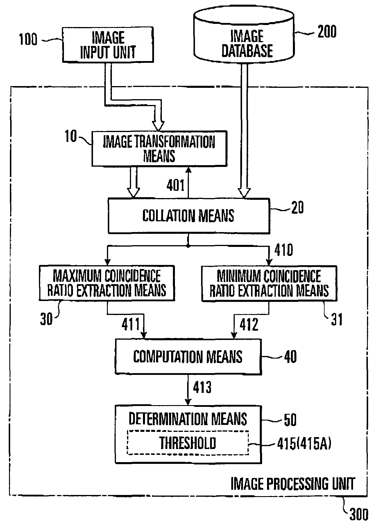
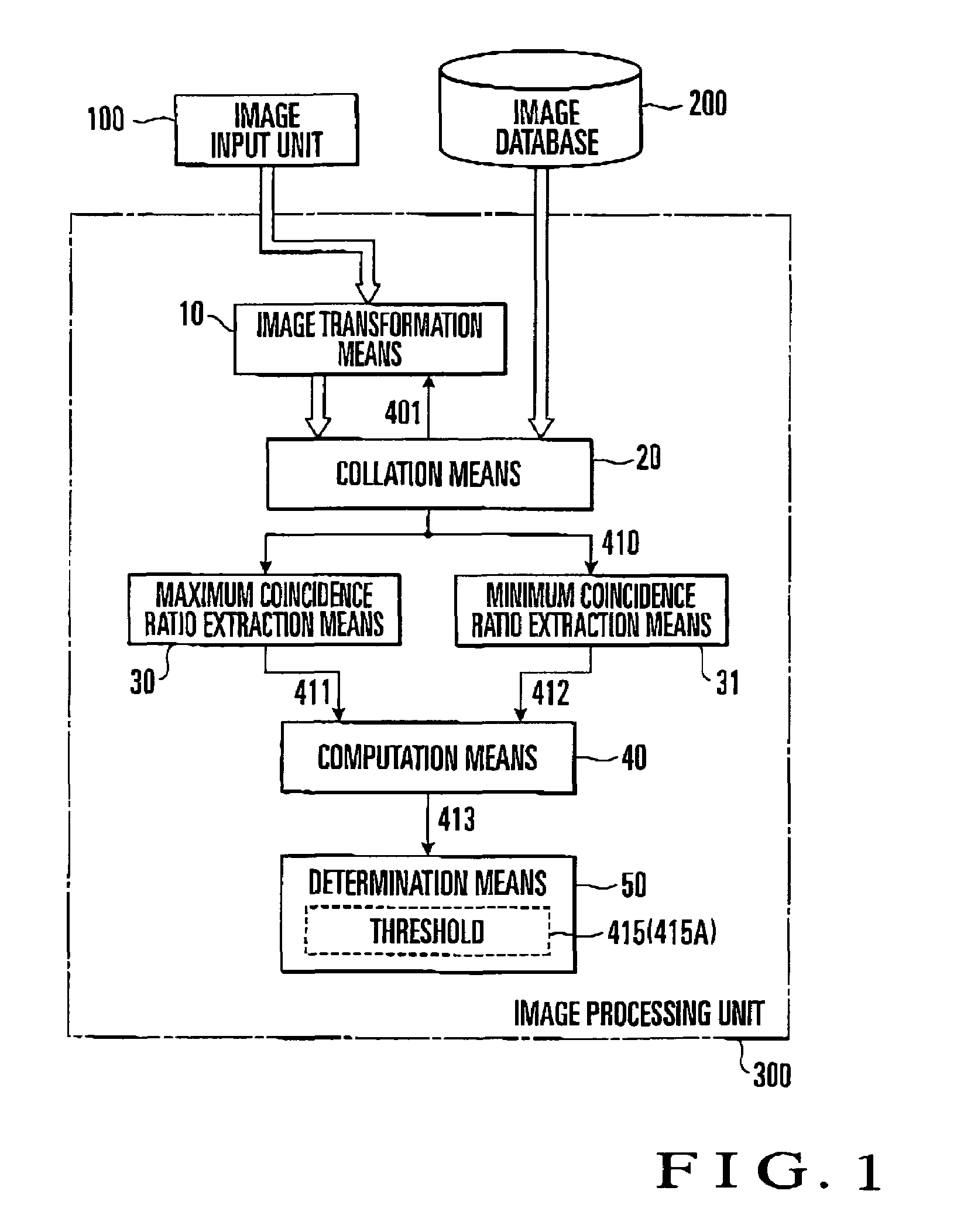
[0062]FIG. 1 shows the arrangement of an image collation apparatus according to the first embodiment of the present invention. This image collation apparatus is comprised of an image input unit 100, image database 200, and image processing unit 300.
[0063]The image input unit 100 detects ridges / valleys of the skin of a finger placed on the sensor (not shown) of the apparatus, and performs image processing such as analog / digital image conversion (A / D conversion) and binarization for a signal output from the sensor. An output from the image input unit 100 is a binary image representing a ridge of the finger skin by a pixel having a luminance corresponding to black (black pixel) and representing a valley of the finger skin by a pixel having a luminance corresponding to white (white pixel). An image output from the image input unit 100 will be referred to as a test image hereinafter.
[0064]The image input unit 100 is comprised of a capacitance detection type fingerprint ...
second embodiment
(Second Embodiment)
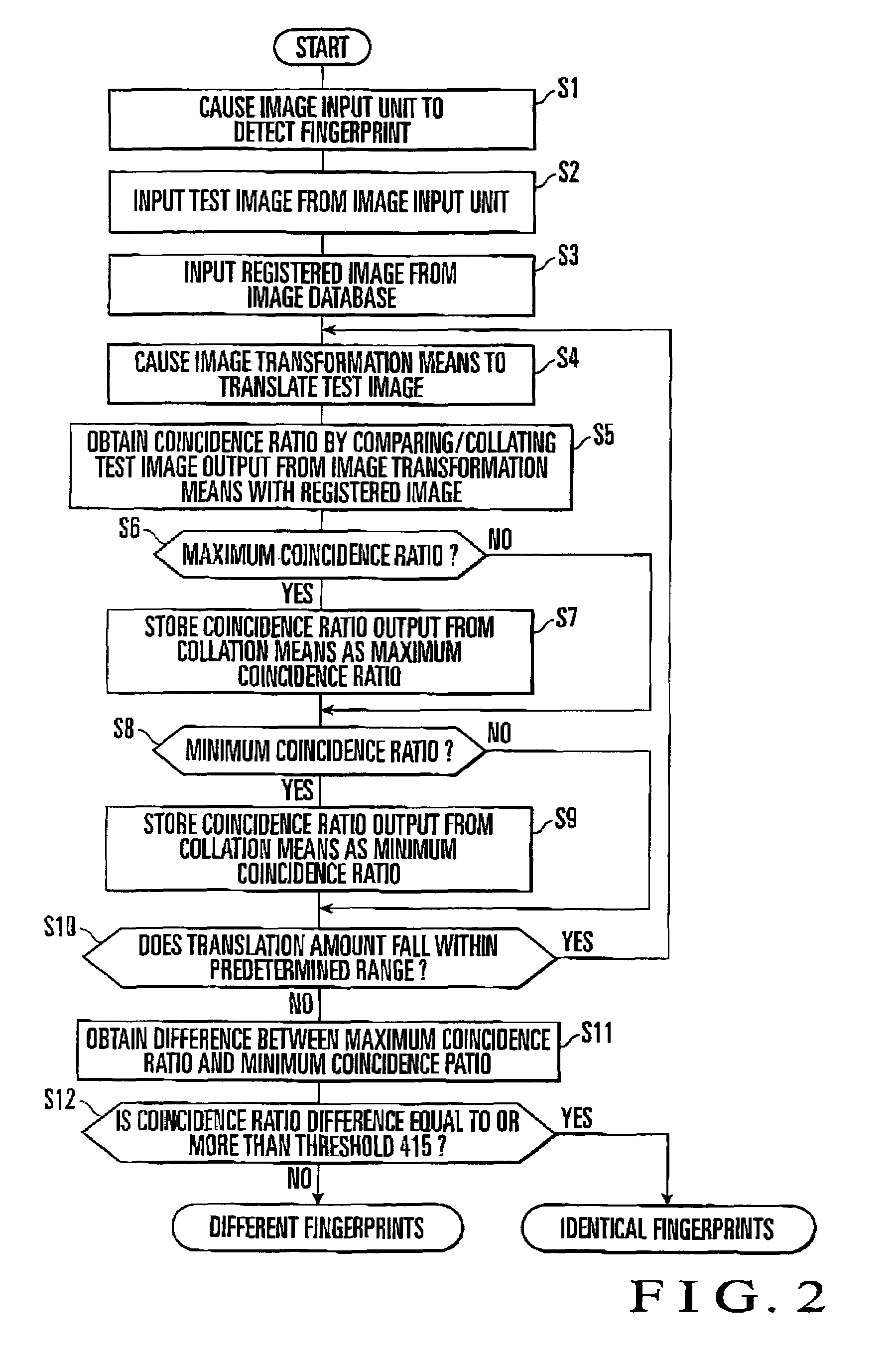
[0084]FIG. 5 shows the collation operation of an image collation apparatus according to the second embodiment of the present invention. The same reference numerals as in FIG. 2 denote the same parts in FIG. 5. The arrangement of the image collation apparatus of the embodiment shown in FIG. 5 is almost the same as that of the first embodiment, and hence will be described with reference to FIG. 1 The differences between this embodiment and the first embodiment are that a computation means 40 of an image processing unit 300 obtains the quotient by dividing a maximum coincidence ratio 411 by a minimum coincidence ratio 412 instead of obtaining a coincidence ratio difference (Da and Db), and a determination means 50 compares the coincidence ratio quotient output from the computation means 40, as a determination index, with a predetermined threshold 415′.
[0085]The operation of the image collation apparatus according to the second embodiment will be described next. The p...
third embodiment
(Third Embodiment)
[0087]FIG. 6 shows the arrangement of an image collation apparatus according to the third embodiment of the present invention. The same reference numerals as in FIG. 1 denote the same parts in FIG. 6. The differences between this embodiment and the first embodiment are that an image processing unit 301 does not have the computation means 40 and has a determination means 51, in place of the determination means 50, which compares a maximum coincidence ratio 411 and minimum coincidence ratio 412 with predetermined thresholds, respectively, and determines that the test image and registered image are identical fingerprint images, only when the maximum coincidence ratio 411 is equal to or more than a first threshold 416, and the minimum coincidence ratio 412 is smaller than a second threshold 417 (first threshold≧second threshold).
[0088]FIG. 7 shows the collating operation of the image collation apparatus according to this embodiment. The same reference symbols as in FIG...
PUM
 Abstract
Description
Claims
Application Information
 - R&D
- Intellectual Property
- Life Sciences
- Materials
- Tech Scout
- Unparalleled Data Quality
- Higher Quality Content
- 60% Fewer Hallucinations
Browse by: Latest US Patents, China's latest patents, Technical Efficacy Thesaurus, Application Domain, Technology Topic, Popular Technical Reports.
© 2025 PatSnap. All rights reserved.Legal|Privacy policy|Modern Slavery Act Transparency Statement|Sitemap|About US| Contact US: help@patsnap.com


