Sensor assembly for determining total temperature, static temperature and Mach number

a technology of total temperature and sensor assembly, applied in the direction of temperature measurement of flowing materials, instruments, heat measurement, etc., can solve the problem that pressure measurement alone cannot determine the true airspeed, and achieve the effect of reducing the number of external probes

Active Publication Date: 2006-04-18
ROSEMOUNT AEROSPACE
View PDF30 Cites 19 Cited by
  • Summary
  • Abstract
  • Description
  • Claims
  • Application Information

AI Technical Summary

Benefits of technology

[0010]A sensor made according to the present invention therefore can reduce the number of external probes and the intrusiveness of probes that are required on an aircraft or other air vehicle for obtaining the necessary parameters for aircraft operation.

Problems solved by technology

Pressure measurements alone would not allow determination of true airspeed.

Method used


Image

  • Sensor assembly for determining total temperature, static temperature and Mach number
  • Sensor assembly for determining total temperature, static temperature and Mach number
  • Sensor assembly for determining total temperature, static temperature and Mach number

Examples


Embodiment Construction

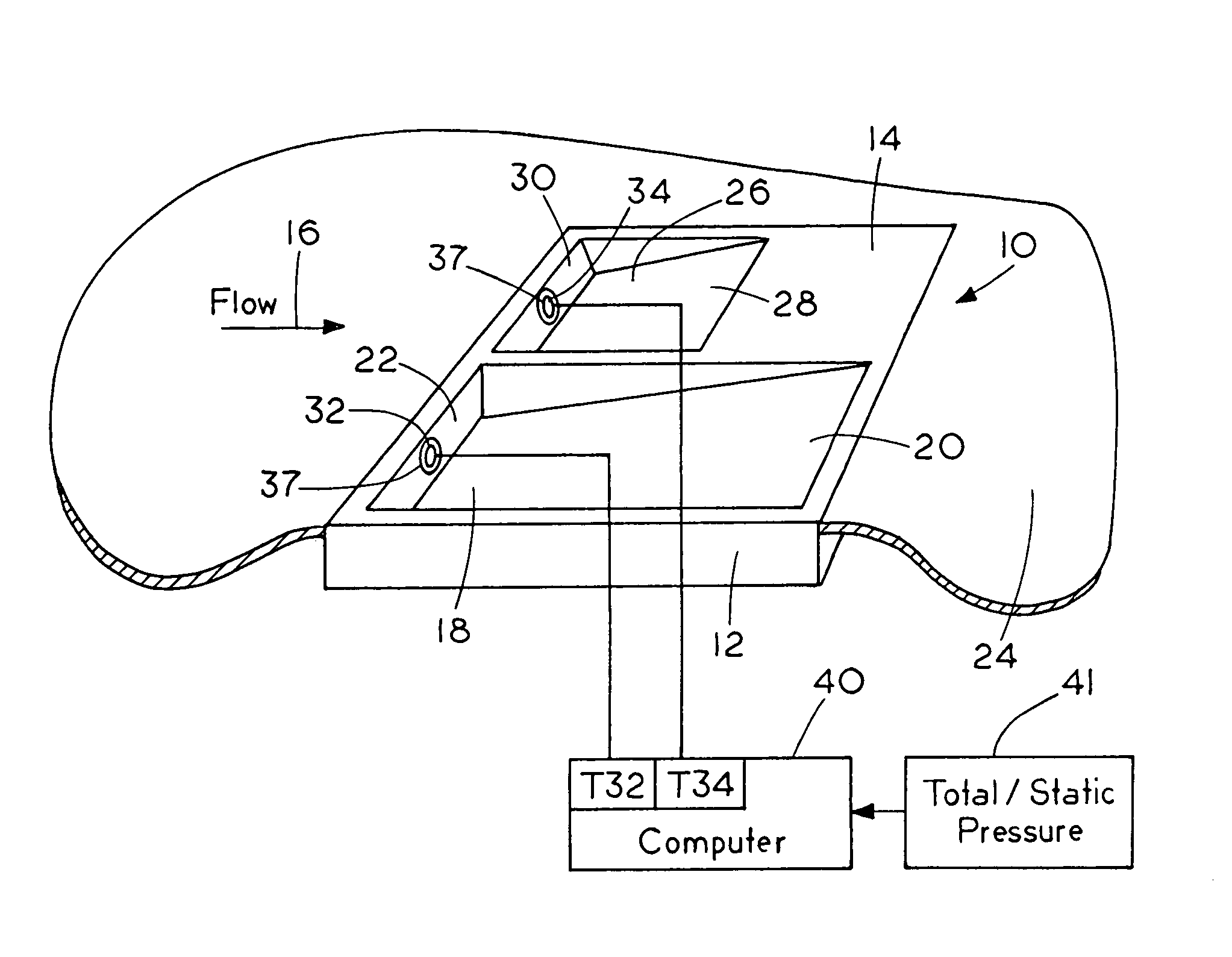
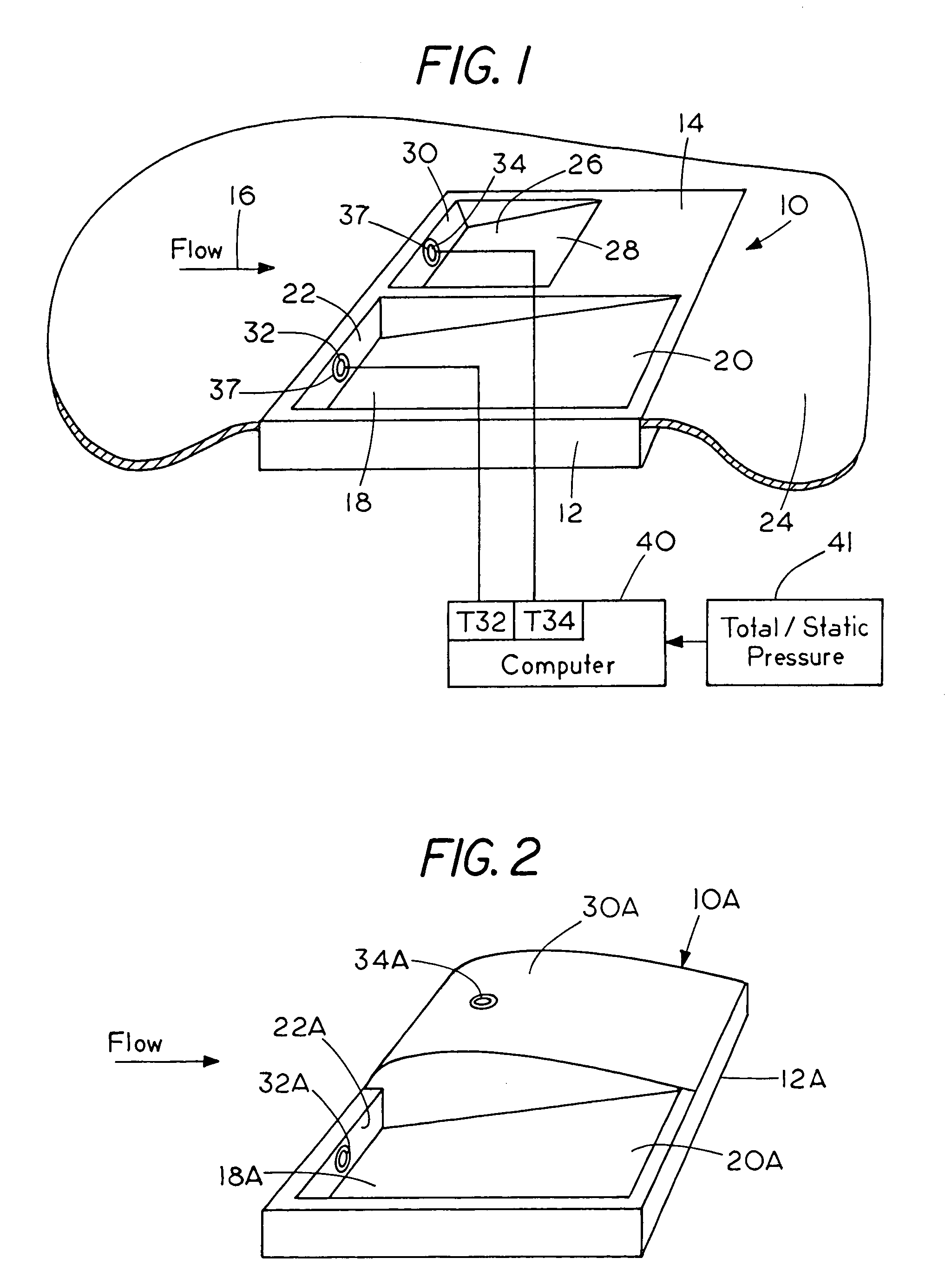
[0018]Referring to FIG. 1, a sensor made according to the present invention is indicated generally at 10. A sensor mounting housing 12 has an exterior surface 14 exposed to airflow that is moving in the direction as indicated by arrow 16. The sensor 10 is designed to be non-obtrusive, or in other words does not project into the air stream outwardly from a support surface a substantial amount. As shown the outer surface 14 of the housing is flush with the surface of a mounting panel 24, such as a skin of an aircraft.

[0019]The housing 12 has a first recess 18 that has a relatively long, gently tapered bottom wall 20 that extends downstream from an inner edge of an upstream wall surface 22 that is substantially normal to the surface 14 and normal to the direction of airflow. The housing 12 also has a second recess 26 in the outer surface 14, that is separate from recess 18. Second recess 26 has a shorter, more steeply inclined bottom wall 28 which extends downstream from an inner edge ...


PUM

PropertyMeasurementUnit
angleaaaaaaaaaa
temperaturesaaaaaaaaaa
temperatureaaaaaaaaaa

Abstract

A temperature sensor is provided with at least two thermometers or temperature sensing elements that have different recovery factors, and which are in the same airflow. The recovery factors for the respective thermometers are determined for the sensor and stored in a memory of a processor. The temperature measured by each of the thermometers is provided to the processor, and the processor establishes ratios using the recovery factors and measured temperatures to determine total temperature and static temperature of the airflow in which the thermometers are placed.

Description

BACKGROUND OF THE INVENTION[0001]The present invention relates to a sensor to determine total temperature, true airspeed and Mach number of an air vehicle moving through an air mass, and the static temperature of the air mass using two or more thermometers or temperature sensing elements with known, but different temperature recovery factors. One relatively unobtrusive instrument permits the determination of these parameters without large, outwardly projecting probes.[0002]It is well known that temperature sensors or thermometers have different temperature recovery factors. The recovery factor of a thermometer is a standard measure that defines how well the thermometer “recovers” the total kinetic energy imparted to it so the thermometer will sense and indicate the true total air temperature in a moving air stream. The recovery factor is the difference ratio of the sensed temperature minus the static temperature to the total temperature minus the static temperature. If all kinetic e...

Claims


Application Information

Patent Timeline
Patent Type & Authority Patents(United States)
IPC IPC(8): G01K1/00G01K13/02
CPCG01K13/028G01K13/02
Inventor SEVERSON, JOHN A.FREEMAN, KENNETH J.CRONIN, DENNIS J.
Owner ROSEMOUNT AEROSPACE
Why Eureka
Try Eureka