Apparatus and method of generating network simulation model, and storage medium storing program for realizing the method

a network simulation and model generation technology, applied in the field of network simulation technology, can solve the problems of user heavy operation load, simulation model may not be generated, complicated network configuration, etc., and achieve the effect of reducing computation cost and facilitating the process of generating

Inactive Publication Date: 2006-04-18
FUJITSU LTD
View PDF6 Cites 43 Cited by
  • Summary
  • Abstract
  • Description
  • Claims
  • Application Information

AI Technical Summary

Benefits of technology

[0027]The present invention aims at generating a simulation model of a network without a database of a model of an appliance. In addition, the present invention aims at generating a simulation model of a network without limit to the information held in the cooperative network management tools. Furthermore, the pre

Problems solved by technology

Furthermore, with network appliances of higher performance, the configuration of a network will be more complicated, and a frame relay network, an ATM (asynchronous transfer mode) network are connected to a router, which is an important network appliance forming part of Internet, thereby increasing the structure of a VPN (virtual private network), an IP over ATM, an IP over SONET, an IP over WTM, etc. in the future.
However, there has been the following problem with the above described conventional system.
In this system, since the user has to check in detail the network whose simulation model is to be generated, and to collect the information required to generate the model, the user has a heavy operation load.
There is the problem with this system that a simulation model may not be generated when the database does not contain a model of a network appliance required for the simulation model to be generated.
Therefore, maintaining the database has a heavy operation load, and the management is costly.
Since collectable information is limited in this system, a simulation model may not be correctly generated with the present situation of the network we

Method used


Image

  • Apparatus and method of generating network simulation model, and storage medium storing program for realizing the method
  • Apparatus and method of generating network simulation model, and storage medium storing program for realizing the method
  • Apparatus and method of generating network simulation model, and storage medium storing program for realizing the method

Examples


first embodiment

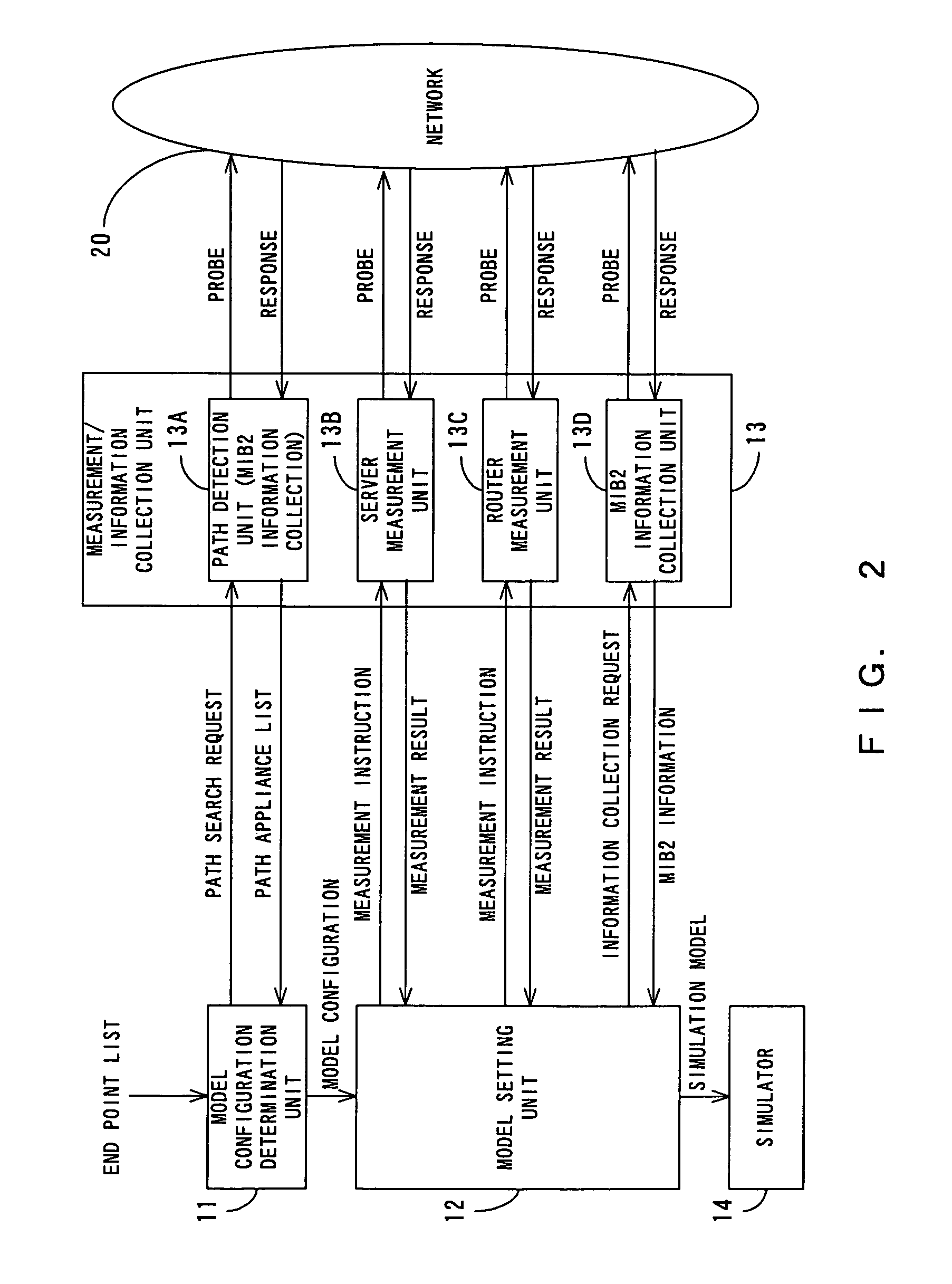
[0072]FIG. 2 is a block diagram showing the system configuration of the simulation model generation apparatus of the network according to the present invention. In FIG. 2, the components also shown in FIG. 1 are assigned the same unit numbers.

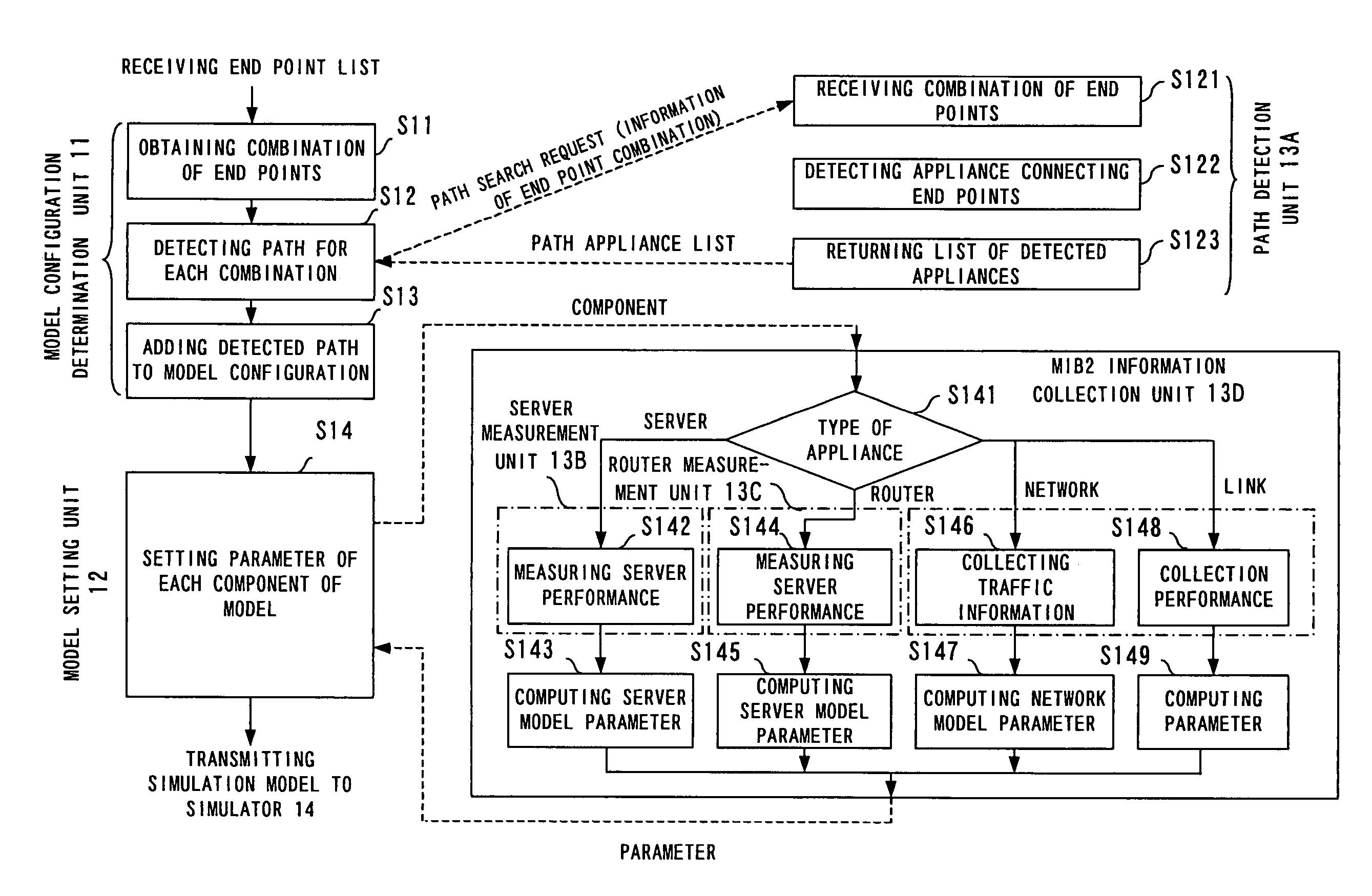
[0073]As shown in FIG. 2, the measurement / information collection unit 13 comprises a path detection unit 13A, a server measurement unit 13B, a router measurement unit 13C, and an MIB2 information collection unit 13D. The function of each of these units is described later. The path detection unit 13A, the server measurement unit 13B, the router measurement unit 13C, and the MIB2 information collection unit 13D can be mounted in separate apparatuses.

[0074]FIG. 3 shows an example of the configuration of the network 20. In FIG. 20, C, C1, and C2 are clients. S, S1, and S2 are servers. R1, R2, and R3 are routers. In FIG. 3, the clients and server connected to respective Ethernets are assigned the same symbols C and S for convenience.

[0075]As shown i...

second embodiment

[0151]FIG. 7 is a block diagram showing the system configuration according to the present invention.

[0152]The topology of the network system shown in FIG. 7 is star-shaped, and centers a network E. Networks A, B, C, and D are connected to the network E.

[0153]Measurement devices 31A, 31B, 31C, and 31D are connected respectively to the networks A, B, C, and D. These measurement devices 31A, 31B, 31C, and 31D correspond to the measurement / information collection unit 13 according to the first embodiment. A model generation device 33 provided in the network E corresponds to the model configuration determination unit 11 and the model setting unit 12 according to the first embodiment. A simulator 34 corresponds to the simulator 14 according to the first embodiment.

[0154]The measurement devices 31A, 31B, 31C, and 31D obtain the measurement information about a server, a router, etc. provided in the networks A, B, C, and D, and the MIB2 information. That is, the model generation device 33 pro...

third embodiment

[0158]Described below is the present invention.

[0159]FIG. 8 is a block diagram showing the system configuration according to the third embodiment of the present invention. In FIG. 8, the network is managed after being divided into three lower networks (subnetworks) A, B, and C. In the example shown in FIG. 8, the network is managed after being divided into three lower networks, but it is obvious that the network can be divided into four or more lower networks according to the present invention.

[0160]A model management device 40 collectively manages simulation models 41A, 41B, and 41C of the three networks A, B, and C.

[0161]A manager is assigned to each of the networks A, B, and C to manage the operation of each of the networks. Each manager manages and operates the corresponding network depending on the conditions of the network.

[0162]The networks A, B, and C comprise model generation / measurement devices 51 (51A, 51B, and 51C) and simulators 52 (52A, 52B, and 52C). The model generat...


PUM


Abstract

Upon receipt of an end point list, a model setting unit requests the measurement/information collection unit to search a path. The model setting unit receives a path appliance list from the measurement/information collection unit, and generates the configuration of a simulation model of a network. The model setting unit selects an appropriate model for each component of the configuration of the simulation model. Then, the model setting unit sets the parameter value of the model based on the measurement result and the collected information received from the measurement/information collection unit, and automatically generates the simulation model of the network.

Description

BACKGROUND OF THE INVENTION[0001]1. Field of the Invention[0002]The present invention relates to a network simulation technology, and more specifically to a network simulation model generation apparatus, method, and a storage medium storing the program for realizing the method.[0003]2. Description of the Related Art[0004]Recently, the scale of networks such as Internet has been quickly extended. In addition, the types of networks have been shifted from voice communications such as telephone, etc. to data communications and multimedia communications. Especially, it is predicted that the multimedia communications capable of transmitting a large volume of data at a high speed will lead this field in the future, and that there will be much heavier traffic in the networks. Furthermore, with network appliances of higher performance, the configuration of a network will be more complicated, and a frame relay network, an ATM (asynchronous transfer mode) network are connected to a router, whi...

Claims


Application Information

Patent Timeline
IPC IPC(8): G06F17/50G06F15/173G06F7/62G06F13/00G06F17/00G06F19/00G06Q10/00G06Q50/00H04L12/24H04L12/26H04L12/70
CPCG06F17/5009H04L41/147H04L41/145H04L41/0853G06F2217/04G06F2111/02G06F30/20
Inventor TAKAHASHI, EIICHIYOKOYAMA, KENTAMURA, NAOHIRO
Owner FUJITSU LTD
Why Eureka
Try Eureka