Eureka AIR delivers breakthrough ideas for toughest innovation challenges, trusted by R&D personnel around the world.

Matrix transposition in a computer system

a computer system and matrix technology, applied in the field of computer science, can solve the problems of complex in-place transposal, inefficient approach, and trivial processing but inefficient, and achieve the effect of reducing the number of steps, and improving the efficiency of the process

Active Publication Date: 2006-04-18
ORACLE INT CORP
View PDF7 Cites 67 Cited by
  • Summary
  • Abstract
  • Description
  • Claims
  • Application Information

AI Technical Summary

Benefits of technology

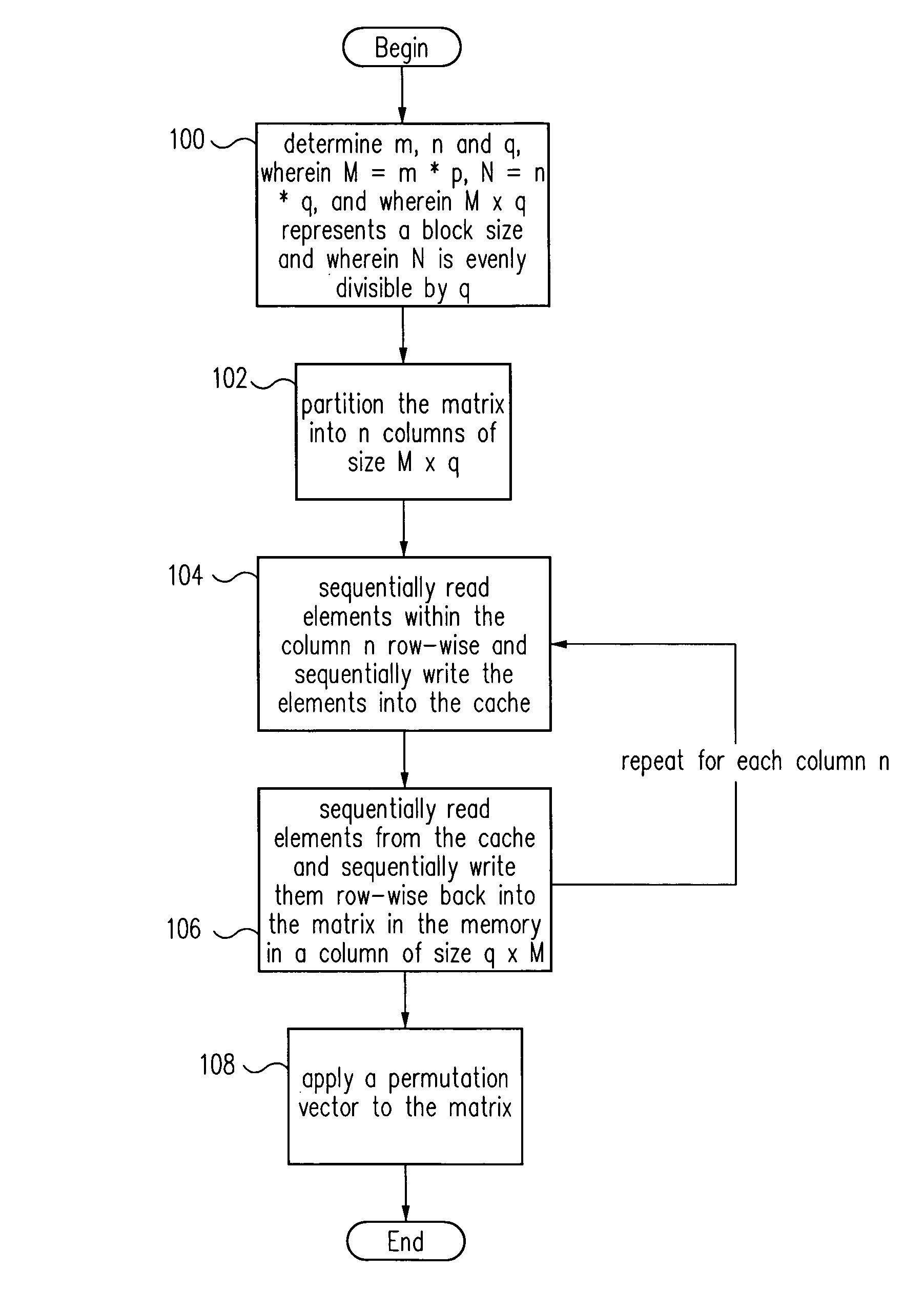
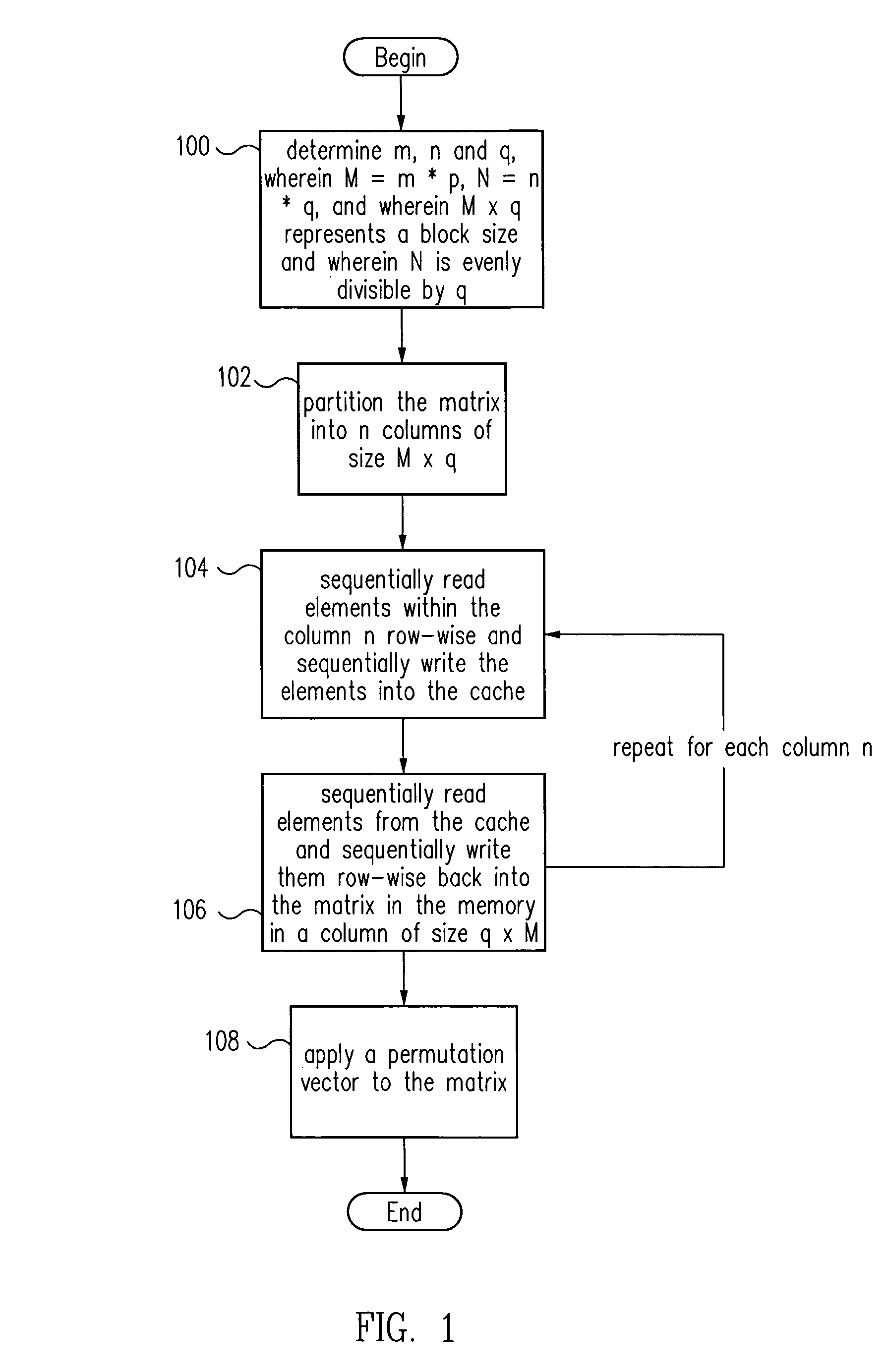
[0040]Improved transposition of a matrix in a computer system may be accomplished while utilizing at most a single permutation vector. This greatly improves the speed and parallelability of the transpose operation. For a standard rectangular matrix having M rows and N columns and a size M×N, first n and q are determined, wherein N=n*q, and wherein M×q represents a block size and wherein N is evenly divisible by q. Then, the matrix is partitioned into n columns of size M×q. Then for each column n, elements are sequentially read within the column row-wise and sequentially written into a cache, then sequentially read from the cache and sequentially written row-wise back into the matrix in a memory in a column of size q×M. A permutation vector may then be applied to the matrix to arrive at the transpose. This method may be modified for special cases, such as square matrices, to further improve efficiency.

Problems solved by technology

If the application requires large data matrices, in-place transpose must be used as there is often not enough memory to hold both a large matrix and its transpose.
The processing is trivial but inefficient.
In-place transpose is much more complicated.
It should be pointed out that is a very inefficient approach.
Simply applying a permutation vector on a large matrix is very expensive.
Computing the permutation vector is a task accomplished via serial processing, and may take a significant amount of time depending on the size and shape of the matrix and the block size used to partition the matrix.
As parallel computing grows in popularity, this delay becomes even more significant.

Method used


Image

  • Matrix transposition in a computer system
  • Matrix transposition in a computer system
  • Matrix transposition in a computer system

Examples


Embodiment Construction

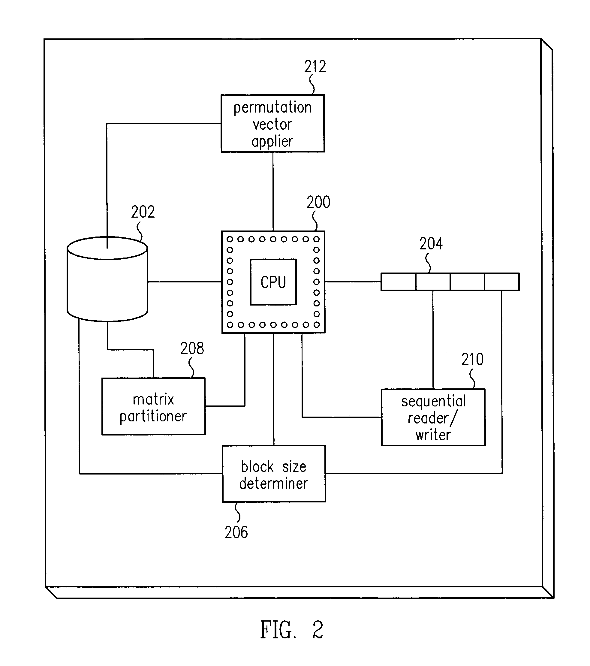
[0052]Embodiments of the present invention are described herein in the context of a system of computers, servers, and software. Those of ordinary skill in the art will realize that the following detailed description of the present invention is illustrative only and is not intended to be in any way limiting. Other embodiments of the present invention will readily suggest themselves to such skilled persons having the benefit of this disclosure. Reference will now be made in detail to implementations of the present invention as illustrated in the accompanying drawings. The same reference indicators will be used throughout the drawings and the following detailed description to refer to the same or like parts.

[0053]In the interest of clarity, not all of the routine features of the implementations described herein are shown and described. It will, of course, be appreciated that in the development of any such actual implementation, numerous implementation-specific decisions must be made in...


PUM


Abstract

Improved transposition of a matrix in a computer system may be accomplished while utilizing at most a single permutation vector. This greatly improves the speed and parallelability of the transpose operation. For a standard rectangular matrix having M rows and N columns and a size M×N, first n and q are determined, wherein N=n*q, and wherein M×q represents a block size and wherein N is evenly divisible by p. Then, the matrix is partitioned into n columns of size M×q. Then for each column n, elements are sequentially read within the column row-wise and sequentially written into a cache, then sequentially read from the cache and sequentially written row-wise back into the matrix in a memory in a column of size q×M. A permutation vector may then be applied to the matrix to arrive at the transpose. This method may be modified for special cases, such as square matrices, to further improve efficiency.

Description

CROSS REFERENCE TO RELATED APPLICATIONS[0001]This application claims the benefit of provisional patent application Ser. No. 60 / 312,201 filed Aug. 13, 2001 in the name of inventors Shandong Lao, Brad R. Lewis, and Michael Boucher and entitled “Matrix Transposition”.FIELD OF THE INVENTION[0002]The present invention relates to the field of computer science. More particularly, the present invention relates to a software program for transposing a matrix in a computer system.BACKGROUND OF THE INVENTION[0003]Matrices are utilized in many different computing processes. There are a number of different operations that may be applied to a matrix. One of the most important operations is the transpose operation. In the transpose operation, the rows and columns of an input matrix are reversed. In formal terms, if A is any matrix whose (i,j)-entry is aij, the transpose of A (denoted AT) is the matrix whose (i, j)-entry is aji, the matrix obtained by reflecting in the main diagonal. This new matrix...

Claims


Application Information

Patent Timeline
Patent Type & Authority Patents(United States)
IPC IPC(8): G06F7/00G06F17/14G06F7/78
CPCG06F7/785
Inventor LAO, SHANDONGLEWIS, BRADLEY ROMAINBOUCHER, MICHAEL LEE
Owner ORACLE INT CORP
Why Eureka
Eureka Blog
Learn More