Common device interface

a common device and interface technology, applied in the field of data processing system software, can solve the problems of significant cost and inconvenience for the system manufacturer, and the code is revised and maintained, and achieve the effect of facilitating the porting of the emulation to a future physical layer

Inactive Publication Date: 2006-04-18
EMC IP HLDG CO LLC
View PDF6 Cites 55 Cited by
  • Summary
  • Abstract
  • Description
  • Claims
  • Application Information

AI Technical Summary

Benefits of technology

[0005]One or more aspects of the invention may include one or more of the following advantages. The control block data structure provides for a common device interface (CDI) between emulations and physical transport drivers. The structure requires that the CDI-compliant emulations and physical transport drivers have knowledge of data transfer direction and data count, but not the underlying meaning or characteristics of the command or response passed down to them from upper level protocol layers. Therefore, the CDI enables the same physical layer driver to be used across multiple emulations and each emulation to be written independently of the underlying physical transport layer. For example, a given emulation can be written using the CDI and then used with a Fibre Channel or a Parallel SCSI driver. Because the physical transport is isolated within the CDI driver, the emulation need not contain undesirable conditional code based on the physical transport layer. Also, porting the emulation to a future physical layer is made easier since all that is needed to support the new physical layer is a new CDI driver. In addition, in a system of interconnected system nodes (e.g., data storage systems), the flexible, generic format of the CDI supports peer-to-peer communications by allowing a system node to act as both a communications originator and responder.

Problems solved by technology

When a new device and associated driver are added to the system, portions of the system software code must be modified, and the revised code tested and maintained, at significant cost and inconvenience to the system manufacturer.

Method used


Image

  • Common device interface
  • Common device interface
  • Common device interface

Examples


Embodiment Construction

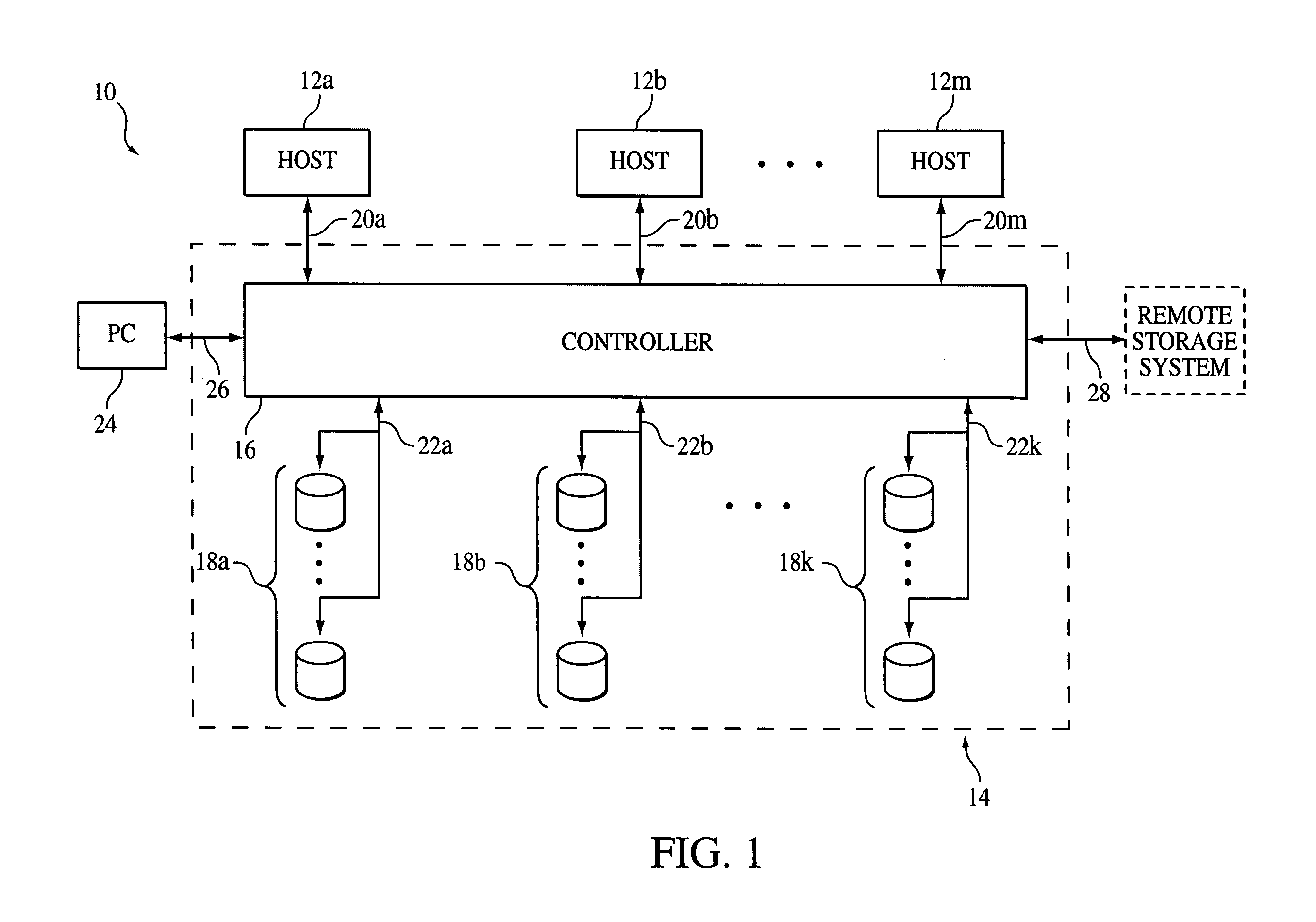
[0022]Referring to FIG. 1, a data processing system 10 includes host computers 12a, 12b, . . . , 12m, connected to a data storage system 14. The data storage system 14 receives data and commands from, and delivers data and responses to, the host computers 12. The data storage system 14 is a mass storage system having a controller 16 coupled to pluralities of physical storage devices shown as disk devices 18a, disk devices 18b, . . . , disk devices 18k. Each of the disk devices 18 is logically divided, in accordance with known techniques, into one or more logical volumes.

[0023]The controller 16 interconnects the host computers 12 and the disk devices 18, and can be, for example, that made by EMC and known as the Symmetrix controller. The controller 16 thus receives memory write commands form the various host computers over buses 20a, 20b, . . . , 20m, respectively, for example, connected and operated in accordance with a SCSI protocol, and delivers the data associated with those comm...


PUM


Abstract

A common device interface for facilitating communication exchanges between physical transport drivers and higher-level software emulations. The common device interface is defined by an input / output control block (IOCB) data structure that allows those portions of different emulations and physical transport drivers that interact with each other to be generic. Thus, the emulation need not know or be concerned with the underlying characteristics of the type of physical transport driver with which it is communicating.

Description

BACKGROUND OF THE INVENTION[0001]The invention relates generally to data processing system software and, more particularly, to device driver software.[0002]Conventional data storage systems are configured with intelligent firmware to control attached system resources such as physical transport devices, e.g., network or storage buses. Typically, the system software must support different code for each of the devices and their drivers. When a new device and associated driver are added to the system, portions of the system software code must be modified, and the revised code tested and maintained, at significant cost and inconvenience to the system manufacturer.SUMMARY OF THE INVENTION[0003]In one aspect of the invention, facilitating data storage system communication exchanges includes providing a control block data structure that is common to different types of physical transport drivers and a higher-level software and using the control block data structure to pass information betwee...

Claims


Application Information

Patent Timeline
Patent Type & Authority Patents(United States)
IPC IPC(8): G06F9/44
CPCG06F3/0607G06F3/0661G06F13/385G06F3/0683G06F3/0664
Inventor MCGILLIS, JAMES M.DECRESCENZO, ROBERTROSNER, TIMOTHY R.CARREL, JOHNMEIRI, DAVID
Owner EMC IP HLDG CO LLC
Why Eureka
Try Eureka